Assembly and Installation
Assembly
Scope of Delivery
The charger delivery includes:
- Pre-assembled charger including cover
- DIN A4 envelope with:
- this operating manual
- Test protocol of the charger
- Drilling template
- Three NFC cards
Installation Location
If possible, the charger should be installed protected from weather conditions. Direct sunlight should be avoided to prevent unnecessary heating of the charger. Adequate ventilation must be ensured. The dust protection cap of the Type 2 plug should not be attached if it could fill with water from rain or similar. In this case, corrosion of the contacts could occur.
Wall Mounting
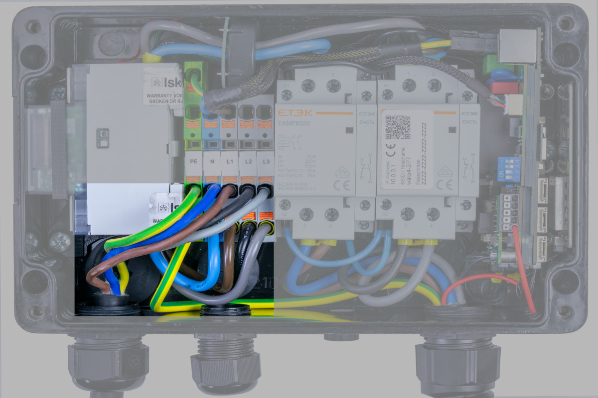
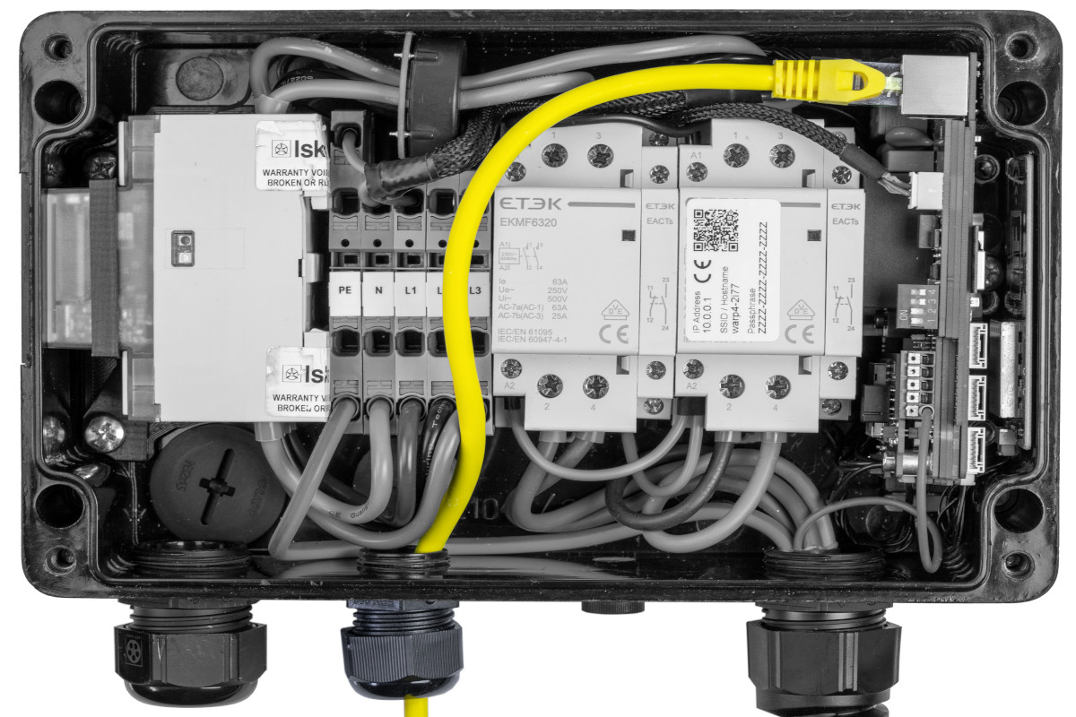
To mount the charger, the cover must be removed. For this, the four Phillips screws (marked red in the image) must be loosened. After loosening the screws, it can be removed from the charger.
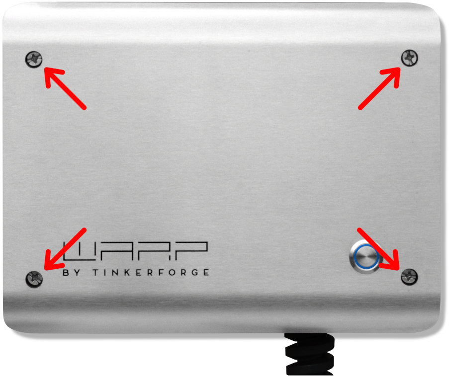
The button in the cover is connected via a cable and must be disconnected from the cable by pressing the latch (marked blue).
![]()
Additionally, the grounding plug (marked green) must be unplugged from the front panel. Only then can the cover be completely set aside.
After removing the cover, the housing can be mounted on the wall. The included drilling template can be used for drilling the mounting holes. When mounting, ensure a sufficiently stable surface.
We recommend using 5 mm or 6 mm screws for mounting. The required screw length depends on the surface. The screw head diameter must not exceed 11 mm, otherwise the screw will not fit through the corresponding opening in the housing. For mounting on a stone wall, for example, 5×80 mm wood screws with 8×50 mm wall plugs can be used.
Requirements for Electrical Installation
The selection of cable cross-section and circuit protection for the charger supply line must comply with national regulations. Typically, the charger is connected three-phase. For this, a three-phase circuit breaker with C-characteristic should be used. For single-phase operation of the charger, a single-phase circuit breaker must be used accordingly. The charger has internal DC fault current detection, which interrupts the charging process at a DC fault current ≥ 6 mA. Therefore, only an upstream Type A 30mA AC residual-current device (RCCB) is necessary. The charger may only be connected in a TN / TT network.
Internal Structure
The structure of the charger differs between the WARP4 Charger Smart and the WARP4 Charger Pro only in the energy meter. Cable entries, the charging electronics, the connection of the supply line at the terminal block and the LAN connection are identical in both versions.
WARP4 Charger Smart
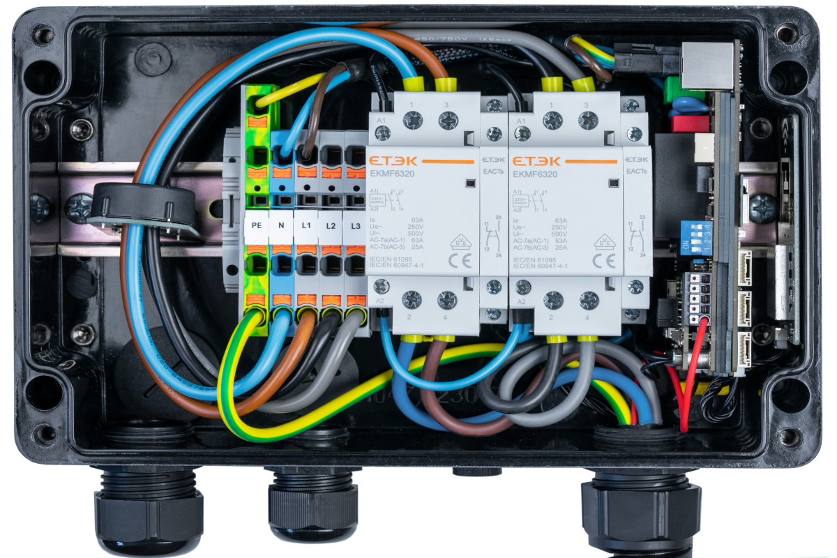
The WARP4 Charger Smart is not equipped with an energy meter and therefore does not have the viewing window for the energy meter on the left side of the housing. At the position of the energy meter, the DC fault current protection is located in this version.
WARP4 Charger Pro
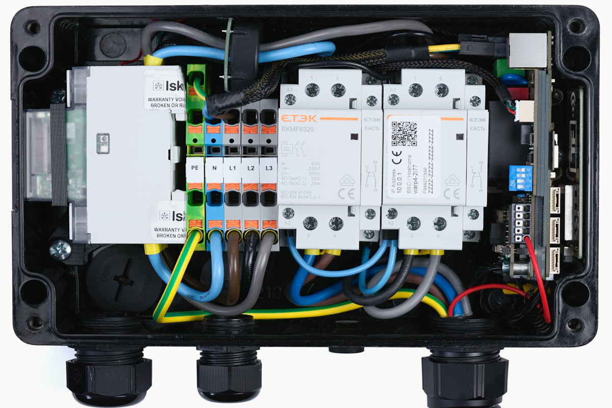
The WARP4 Charger Pro is equipped with an Iskra WM3M4 energy meter. This is mounted horizontally and is visible from the outside through a viewing window on the left side of the housing.
Electrical Connection
The work described in this section may only be performed by a qualified electrician.
After the charger has been mounted, it can now be connected. The cover must be removed for this.
Connecting the Supply Line
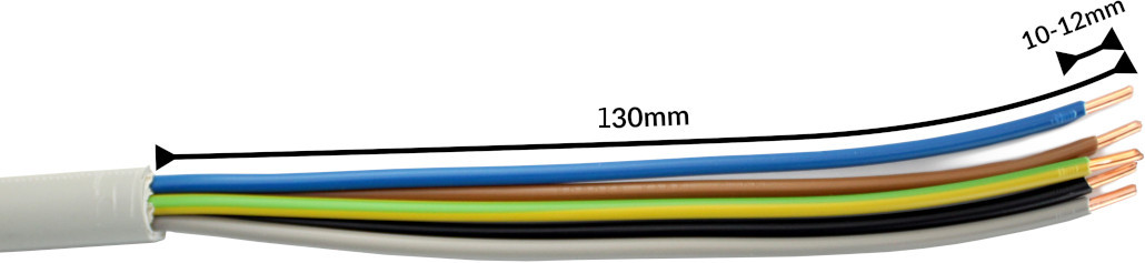
The supply line should be prepared for all variants as shown in the photo above. We recommend stripping the cable to a length of at least 130 mm. For the terminals, a stripping length of 10 mm to 12 mm is specified.
The supply line is connected to the internal terminal block. To offer maximum freedom of movement with rigid conductors, the wires are routed in a small loop over the terminal block and connected to the free spring terminal positions. The wires are inserted into the terminals according to the sequence and terminal labels.
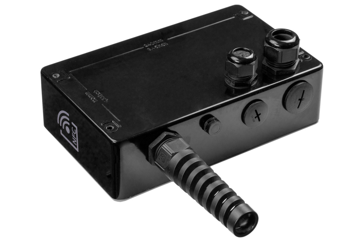
Finally, the cable gland must be tightened. The gland has a clamping range of 11 mm to 22 mm and should be tightened to 10 Nm according to the manufacturer.
The correct seating of the wires and phase assignment must be checked after installation! All connections within the charger must be tightened. Next, the maximum charging current must be set.
Cable Entry from the Rear
The cable entry of the WARP4 Charger from the bottom (delivery state) can be converted so that cable entry is from the rear. For this, the cable gland (M32) for the supply line and the cable gland for the network cable must be unscrewed from the charger housing. The holes in the rear of the charger are sealed from inside with blind plugs in the delivery state. These must be removed and screwed into the now open holes at the bottom. The cable glands are then screwed into the charger housing from the rear.
Variant with Factory-Connected Supply Line
If the charger is ordered with a pre-installed supply line from the factory, it must be connected outside the charger. The colors are assigned according to DIN and as follows: L1 brown, L2 black, L3 gray, N blue, PE yellow/green.
The correct seating of the wires and phase assignment must be checked after installation! Then the maximum charging current must be set.
Single-Phase Operation
All chargers can also be connected and operated single-phase. For this, phase L1 must be connected, as it is also used for power supply to the charger. L2 and L3 are only switched through by the charger and can therefore remain unconnected.
A WARP4 Charger Smart or Pro should be configured for single-phase operation in the web interface.
Setting the Charging Current
The maximum allowed charging current must be set depending on the house-side circuit protection. The charging current must not be set higher than allowed by the supply line or circuit protection.
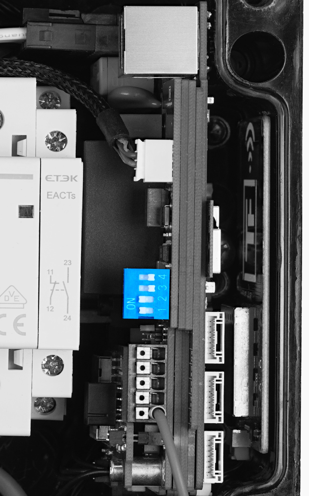
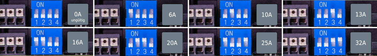
To set the charging current, the cover must be opened. The maximum charging current is set via four DIP switches on the right of the charge controller (EVSE) as follows (maximum allowed charging current in gray):
In factory state, the switches are set so that the charger is inactive ("invalid"). As an example, in the second row, switch 1 is set to "ON" and switches 2, 3 and 4 are set to "OFF". This sets a maximum charging power of approx. 4 kW (3×6 A) for three-phase operation. If the charger is only connected single-phase, the vehicle can draw a maximum of 1.4 kW (1×6 A) via the charger.
The switch position and associated maximum charging current may only be changed after installation by a qualified electrician taking into account the mentioned conditions!
Creating LAN / RJ45 Cable
To connect the WARP4 Charger via LAN, a LAN / RJ45 cable must be prepared. The RJ45 cable can be routed into the charger using an M25 cable gland. On the charge controller (on the right in the charger) there is an RJ45 socket where the routed cable can be plugged in. We recommend routing the cable in an arc to the left over the terminal block. Larger plugs, for example tool-free or RJ45 plugs with an LSA connection, can also be used.
The M25 cable entry has a sealing plug with holes for two cables. A patch cable can also be inserted through the M25 gland. However, the sealing plug must then be slit for this.
Testing
Each charger was individually tested at the factory according to IEC 60364-6 and the corresponding valid national regulations; the respective test protocol is included. Nevertheless, a test of the entire installation according to the same regulations is necessary before initial commissioning.
When measuring insulation resistance, a lower value is measured for L1 (approx. 1 MΩ), as the installed charge controller has an optocoupler with a 1 MΩ series resistor between L1 and PE (grounding monitoring). If an EVSE adapter is used during measurement, erroneous measurements on L2, L3 and N (measured against PE) may occur due to the mentioned monitoring circuit in interaction with the EVSE adapter. If this is the case, the insulation measurement must be performed without an EVSE adapter directly at the Type 2 plug.
The internal DC fault current detection is automatically tested by the charger.
After the charger has been installed and the correct electrical installation has been verified, the charger can be commissioned. In the first step, the power supply to the charger is switched on. The LED then flashes very quickly in magenta. The charger performs a calibration of the DC fault current detection during the first three seconds. After completing this calibration, the LED lights up continuously. The charger is now ready for operation. If the LED does not now light up permanently in blue, an error has been detected.
Next, an electric vehicle can be connected to the charger for charging. To do this, the protective cap is removed from the charging plug and the plug is inserted into the charging socket of the electric vehicle. After a few seconds, a contactor in the charger should audibly switch and the vehicle should indicate the start of the charging process. During charging, the LED "breathes" blue. When charging is complete, it lights up permanently. After approx. 15 minutes of inactivity, the LED is switched off.
Controls
The RGB LED built into the front button can assume different colors depending on the operating state. The behavior when the button is pressed can be configured in the charger web interface.
Additionally, the charger has an NFC module, installed on the right side of the housing, that allows charging authorization e.g. via chip card. A detailed description can be found in the section user management.
The WARP4 Charger Pro has a window on the left side of the housing through which the display of the installed energy meter is visible.
EVSE Terminal Block / Shutdown Input
On the right in the charger is the charge controller. Next to the DIP switch where the maximum charging current is set, there is a terminal block. The CP line of the Type 2 charging cable is connected to this.
Additionally, there is the shutdown input ("EN") here. This input
must be short-circuited with PE to be active. PE is available multiple
times on the terminal block. The interpretation of the shutdown input
can be defined under Charger → Settings under the item "Shutdown input".
For use as a controllable consumption device, see
Controllable Consumption Device according to §14a EnWG.
The terminal block assignment is labeled.
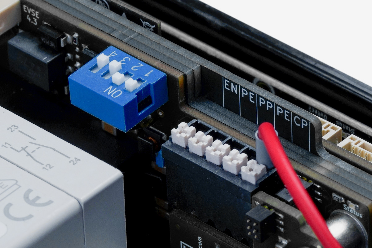
Between the DIP switch and the terminal block there is a small jumper. This is used to configure whether a 16A charging cable (11 kW) or a 32A charging cable (22 kW) is installed. Using the third possible position of the jumper, the PP input on the terminal block can also be selected. A standard-compliant resistor must then be placed between PP and PE to configure the maximum current of the charging cable. The correct position of the jumper is also labeled on the circuit board.