Troubleshooting
Error states are indicated by the charger through the blue LED in the cover. For the WARP2 Charger Smart and WARP2 Charger Pro variants, the web interface or the status page of the charge controller provides further information.
Error Diagnosis
Blue LED is off
There are various possible causes for this error state:
- The blue LED turns off after about 15 minutes of inactivity. Pressing the button or connecting an electric vehicle wakes the charger again and the LED should light up permanently again.
- The charger is not powered. Possible causes: power outage, fuse or residual current circuit breaker has tripped.
- The internal charge controller is without power. The charger has two internal fine fuses; one may be defective.
- The internal connection cable to the cover was not plugged in correctly (e.g., rotated 180° at the button).
Blue LED flashes very quickly
After switching on the power supply, the charger calibrates the DC fault current detection. After three seconds, the calibration should be complete and the blue LED should light up permanently (ready for operation).
Blue LED flashes twice at intervals, web interface shows switch error
The charger was not installed correctly. The switch setting of the charge controller is still at factory state. See section Setting the Charging Current.
Blue LED flashes three times at intervals, web interface shows DC error
A DC fault current was detected. The error can be reset either via the charger's website or by briefly disconnecting the charger's power supply. Caution: observe the note on DC fault currents in the section Protective Devices of the Charger!
Blue LED flashes four times at intervals, web interface shows contactor error
There are various possible causes for this error state:
- Grounding fault of the charger (possibly PE not correctly connected?)
- Phase L1 without voltage (possibly L1/N reversed?)
- Contactor does not switch on correctly (no voltage at L1 after the contactor), no contact.
- Contactor does not switch off correctly (voltage from L1 is still present after the contactor despite switching off), "contactor is stuck".
- One of the two internal fine fuses is defective.
Blue LED flashes five times at intervals, web interface shows communication error
There is a communication error with the electric vehicle. If this occurs for the first time, disconnect the charging cable from the vehicle, wait 10 seconds and reconnect the charging cable to the vehicle (restart charging process). If the problem persists, there can be various reasons for it:
- There is a fault with the charging cable (short circuit, dirty / moist contacts, etc.). The charger must then be taken out of operation immediately and repaired.
- There is a technical defect in the vehicle.
- There is a technical defect in the charger (charge controller defective, etc.).
- The vehicle requests IEC 61851-1 status "D - Charging with ventilation". This mode is not supported by the charger.
- The vehicle transmits IEC 61851-1 status E or F. In both cases, this is an error that the vehicle has detected.
The charger is not reachable via LAN / WLAN, but the blue LED is lit
In this case, check whether the charger has possibly gone into access point fallback. As in factory state, the charger then opens its own WLAN. If the access data has not been changed, it corresponds to the factory settings and can be found on the sticker on the back of the manual.
Recovery Mode
If the charger neither opens its access point nor can the web interface be accessed via a configured network, you can start recovery mode as follows:
- Power off the charger.
- Hold down the button in the cover.
- Restore power to the charger (possibly with a second person).
- Hold the button for at least 10, but maximum 30 seconds.
The charger then starts in recovery mode. First, the network settings are deleted and login is disabled. It should then be possible to access the charger again via the access point.
By disconnecting and reconnecting the power supply within the first minute in recovery mode, a factory reset can be triggered.
Factory Reset
If the web interface does not function correctly or the configuration is defective, you can reset all settings to factory state on the Firmware Update subpage.
A factory reset will lose all configurations, created users, learned NFC tags and tracked charging processes.
After the reset, the web interface restarts and opens the access point with the SSID and passphrase noted on the sticker. The charger can now be configured again.
To prevent tracked charging processes from being lost, alternatively only the configuration can be reset. Created users (but not the user history of the charge tracker) and NFC tags are still deleted.
If the web interface can no longer be reached, the following options exist:
If a network connection can be established but the web interface itself no longer works, an attempt can be made to open the recovery page. If you are connected via the access point of the charger, you reach the recovery page at http://10.0.0.1/recovery. With an existing connection to a LAN or WLAN, you reach the page at http://[configured_hostname]/recovery, e.g. http://warp2-ABC/recovery. Using the recovery page, you can restart the charger, install firmware updates, reset the charger to factory state (Factory Reset), download debug reports and use the HTTP API.
Re-flashing the Charger
Alternatively, you can re-flash the charger (more precisely: the installed ESP32 Ethernet Brick). For this, a PC with installed Brick Viewer 2.4.20 or newer is required. You can find this at https://www.tinkerforge.com/en/doc/Software/Brickv.html. In addition, a USB-C cable is required to connect the Brick to the PC. Brick Daemon is not required. To re-flash, proceed as follows:
- Power off the charger.
- Remove the charger cover as described in the Wall Mounting section.
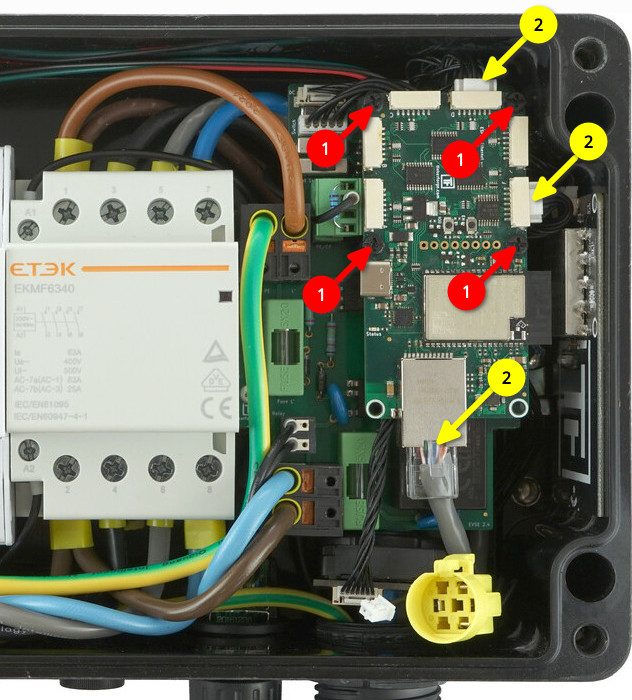
- The ESP32 Ethernet Brick is located on the right in the charger. Unscrew the four black plastic screws (1) and disconnect the LAN cable as well as the two Bricklet cables with white plug (2). The ESP32 Ethernet Brick can then be taken out of the charger.
- The ESP32 Ethernet Brick must then be connected to the PC via USB-C and the Brick Viewer must be started.
- Then click on Updates / Flashing at the bottom left and then on Brick at the top.
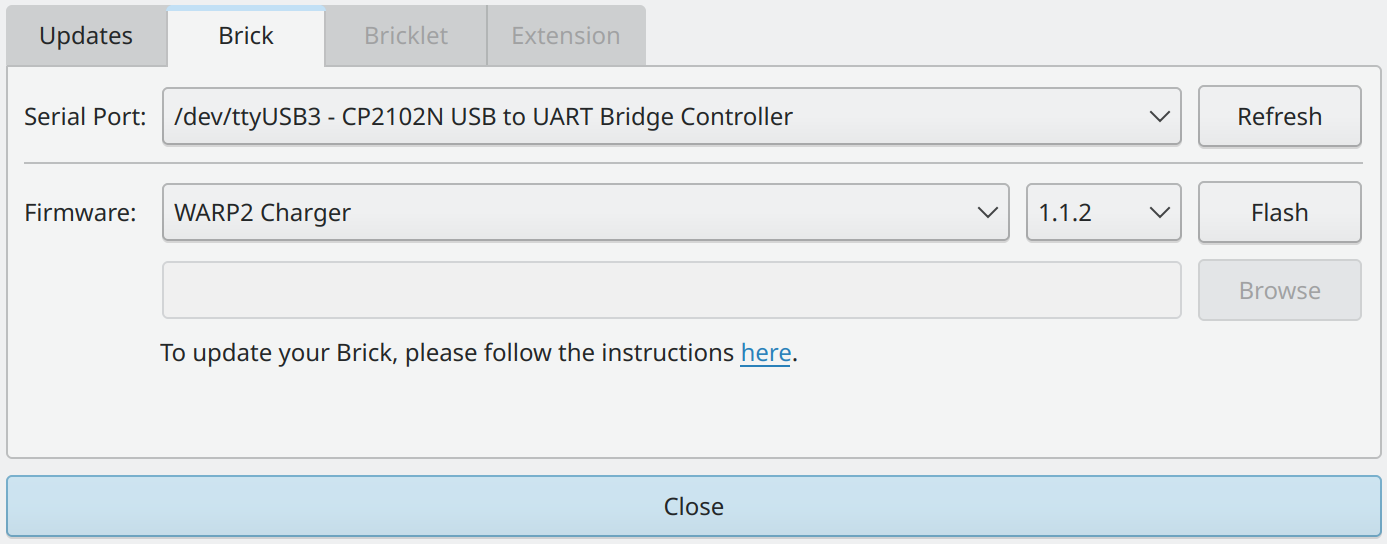
- At Serial Port, select the port to which the Brick is connected. Typically, only one port should appear in the list. The correct port is one at which a "CP2102N USB to UART Bridge Controller" or an "ESP32 Ethernet Brick" is listed.
- Under Firmware, select the "WARP2 Charger". The current firmware version is selected automatically.
- Click on "Flash". The flash process is finished when the status LED of the ESP32 Ethernet Brick begins to flash blue.
- After the Brick has been re-flashed, it can be disconnected from the PC and installed in the charger as follows.
- First, plug the white Bricklet plugs as well as the LAN cable back in.
- Then screw the Brick onto the corresponding spacers with the plastic screws.
- Now close the charger by first connecting the button in the cover as well as the grounding plug. Then put the cover on and tighten the four screws.
- The charger can now be powered again. If the flash process was successful, the charger should now open the WLAN access point again and can be set up.
Solving Charging Problems
If charging interruptions occur, this can have various causes. Possible causes can be a faulty installation of the charger or a technical defect of the charger or the vehicle. The following points should be checked:
- Type 2 plug seating: A Type 2 plug that is not fully inserted can cause a vehicle not to charge or only to charge in an emergency charging mode with minimal power. An indication of this can be that the vehicle does not correctly lock the Type 2 plug.
- Inspection of all components: All components should be checked for damage and moisture.
- Charger web interface: Only available for the Smart and Pro variants. The status page indicates the charging status, the allowed charging current and the reason for any limitations from the charger's perspective. More detailed information is provided on the Charging Status subpage. A charging log can also be generated here, which records all values of the charging process.
- Measurement by an electrician: Electrical problems can be diagnosed by an electrician. They can check whether all conductors are correctly connected.
Load Management Errors
When using load management, two types of errors can occur: charger errors that only affect a specific charger, and management errors, on whose occurrence charging is stopped at all controlled chargers.
Charger errors must be resolved at the corresponding charger. The Error Diagnosis helps here. The diagnosis of management errors is explained below:
- Communication error / Charger not reachable: A charger cannot be reliably reached. There may be a connection problem. In this case, check the network connection or the network cable and the IP configuration of the charger.
- Firmware incompatible: Load management requires compatible firmware on all participating chargers. The respective latest firmware versions should be compatible with each other, even when WARP(1) and WARP2 Charger are used in a load management network.
- Load management disabled: Load management is disabled on one of the chargers to be controlled. This means no control by the load manager is possible. Load management can be enabled on the charge controller subpage.
- Charge controller not reachable: The charge controller of a charger cannot be reached, but the charger itself can. In this case, the event log of the affected charger should be checked.
- Charge controller not responding: The charge controller of a charger does not respond to current allocations. Load management may be disabled on it.
Spare Parts
Spare parts for the WARP2 Charger are available in our shop:
| Article number | Component |
|---|---|
| WARP-CON-4P-63A | Contactor 4-pole, DIN rail, 63 A |
| WARP2-METER-3PH-MID | Bidirectional three-phase meter, 3 phases, RS485, MID |
| WARP-T2-5M-16A | Type 2 plug with 5 m cable, 11 kW / 16 A |
| WARP-T2-5M-32A | Type 2 plug with 5 m cable, 22 kW / 32 A |
| WARP-T2-75M-16A | Type 2 plug with 7.5 m cable, 11 kW / 16 A |
| WARP-T2-75M-32A | Type 2 plug with 7.5 m cable, 22 kW / 32 A |
| WARP-FUSE-0.5A | 2x fine fuse 5×20 mm, medium time-lag, 0.5 A |
| WARP-ETH-FEED-THR | Ethernet housing feed-through |
| WARP-NFC-STICKER | NFC sticker |
| WARP2-DC-PROTECT | DC residual current protection module (6 mA) |
| WARP2-CASE | WARP2 housing |
| WARP2-CABLE-HARNESS | WARP2 cable harness |
| WARP2-TERMINAL-BLOCKS | WARP2 terminal block assembly |
| WARP2-NFC-CARD | 3× WARP2 NFC cards |
| WARP2-SCREWS | WARP2 screw set |
| WARP2-PB-LED | WARP2 button/LED |
| WARP-RES-220 | Resistor 220 Ω |
| WARP-RES-680 | Resistor 680 Ω |
| WARP2-ESP32-ETH | ESP32 Ethernet Brick with WARP2 firmware |
| 2167 | EVSE Bricklet 2.0 |
| 286 | NFC Bricklet |
| 6150 | Bricklet cable 15 cm (7p-7p) |
| 6149 | Bricklet cable 6 cm (7p-7p) |
Fuse Replacement
The charger is internally protected by two 5×20 mm fine fuses (medium time-lag (m), 500 mA). Tinkerforge uses fuses of type "ESKA 521.014".