Interfaces
With the exception of energy meters compatible with the WARP Energy Manager, which can be directly connected to it, all other interfaces are accessed via the network (LAN, WLAN).
The following is a list of compatible interfaces:
SunSpec
SunSpec is a communication standard for PV inverters. WARP Charger and WARP Energy Manager can directly read SunSpec devices via LAN or WLAN.
If an inverter or energy manager is present that has access to an energy meter at the grid connection, it can often be read via SunSpec over the network.
SunSpec offers the advantage that compatible devices can be directly detected and read by the WARP Charger and WARP Energy Manager. During configuration, only SunSpec needs to be selected as the class and the IP address of the device needs to be entered. The system lists all detected devices so that they can be easily assigned.
Modbus/TCP
Not all devices support SunSpec. We are working to support the most important devices that cannot be used via SunSpec. Access via Modbus/TCP over LAN or WLAN is another widely used option and is supported by many devices.
Four different models for virtual energy meters are available: Inverter, Grid Connection, Storage, and Load. Depending on the device, only some of these meters are available.
Modbus/TCP is also used to control battery storage systems.
With Modbus/TCP, information must be provided about which registers need to be read and how the values need to be interpreted. There are two options for this:
Predefined Register Table
For devices known to us, we have already predefined register tables. If these are available, only the corresponding preset needs to be selected and the provided meters need to be assigned. These devices are listed in the following table with the protocol Modbus/TCP.
A technical insight into the respective implementations can be found on Github ESP32-Firmware prepare.py
Custom Register Table
If we do not yet provide a device-specific register table, it can also be defined manually. In the custom settings, only the address mode needs to be specified and then the desired registers can be created. The register type, an offset (shift), a scaling factor (float), and the assignment to a meter value (e.g., Active Power L1) can be defined. In principle, any Modbus/TCP-capable device should be supported this way.
For PV excess charging, an energy meter must be configured that contains at least the following value: "Active Power (Import minus Export); Σ L1, L2, L3 [W]
This value is used for control. Additional values can be configured but are not technically necessary.
For dynamic load management, an energy meter must be configured that contains at least the following values:
- "Current (Import minus Export); L1 [A] or "Current (Import plus Export); L1 [A] or "Current (Import); L1 [A]
- "Current (Import minus Export); L2 [A] or "Current (Import plus Export); L2 [A] or "Current (Import); L2 [A]
- "Current (Import minus Export); L3 [A] or "Current (Import plus Export); L3 [A] or "Current (Import); L3 [A]
These values are used for control. Additional values can be configured but are not technically necessary. Whether "Import", "Import minus Export", "Import plus Export" must be selected depends on the respective energy meter. This can be tested if in doubt.
Modbus/RTU (Converter)
Not all devices support Modbus/TCP. Especially older devices communicate via Modbus/RTU, a two-wire RS485 bus. Thus, these devices cannot simply be read over the network. However, there are converters that can convert an RS485 bus to LAN or WLAN. If such a converter is placed between the Modbus/RTU (RS485) connection of the device and the network (LAN, WLAN), the device can be read via Modbus/TCP.
Known Converters
Below is an excerpt of various converters with the most important setup steps.
Ebytes NB114
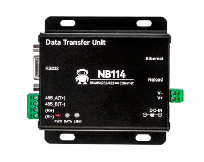
This converter can be screwed open and converts between Modbus/TCP and Modbus/RTU. It does not have WiFi but has a LAN connection. By default, the converter is delivered with a static IP setting. The IP is 192.168.3.7. The login credentials for the web interface are admin:admin. The following settings must be configured:
- Open http://192.168.3.7, credentials admin:admin. If not reachable, press the "Reload" button on the device.
- Under "Network parameter" set Work Mode to "TCP Server", Port 502.
- Under "Serial parameter" configure the settings for the respective inverter (often 9600 8N1).
- Under "Modbus parameter" set "MODBUS TCP to RTU" to "Open".
Elfin EW11
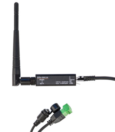
The Elfin EW11 is a small WiFi dongle that can convert between Modbus/TCP and Modbus/RTU. The following setup steps are necessary:
- Connect to AP (typically EW11_XXXXX). No password necessary.
- Open http://10.10.100.254, credentials admin:admin
- Under "System Settings" configure AP+STA and set up STA WiFi
- Under "Serial Port Settings" configure the settings for the respective inverter (often 9600 8N1), Protocol Modbus, CLI Disable
- Under "Communication Settings" create a TCP server on port 502 with Route "Uart" and save. The already predefined "netp" can be used for this.
Eltako ZGW16WL-IP
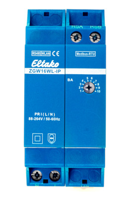
The Eltako ZGW16WL-IP is a Modbus/TCP to Modbus/RTU gateway. It has a width of 2TE and has an Ethernet connection.
PUSR USR-DR302
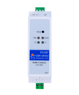
This converter can be mounted on a DIN rail and converts between Modbus/TCP and Modbus/RTU. It does not have WiFi but has a LAN connection. The following setup steps are necessary:
- By default, DHCP is configured for the LAN connection. The credentials for the web interface are admin:admin.
- Under "Serial Port" configure the settings for the respective inverter (often 9600 8N1), Work Mode TCP Server.
Waveshare RS232/485 To WIFI ETH (B) or Waveshare RS232/485 To WIFI POE ETH (B)
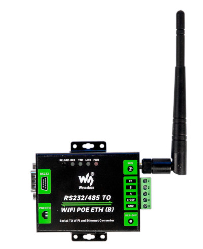
This converter has both WLAN and Ethernet and converts between Modbus/TCP and Modbus/RTU. It can be screwed anywhere using two brackets, but can also be mounted on a DIN rail using the included DIN rail holder. There is a PoE-capable version. Apparently, the converter is delivered with a static IP setting. The IP is 192.168.1.200. The password for the web interface is admin. The Waveshare Wiki provides more information. Additional settings can be made via the VirCom tool from Waveshare. This tool also allows determining the converter's IP address.
The following setup steps are necessary:
- Open http://192.168.1.200, password admin. If not reachable, search for another IP.
- Under "Network Settings" set Work Mode to "TCP Server".
- Under "Serial Settings" configure the settings for the respective inverter (often 9600 8N1).
- Under "Multi-Host Settings" set Protocol to "Modbus TCP to RTU" and "Enable Multi-host" to "True" if other devices should also access the inverter.
Waveshare RS485 To ETH (B) or Waveshare RS485 To POE ETH (B)
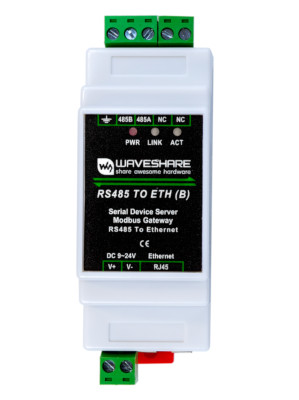
This converter can be mounted on a DIN rail and converts between Modbus/TCP and Modbus/RTU. It does not have WiFi but has a LAN connection. There is a PoE-capable version. Apparently, the converter is delivered with a static IP setting. The IP is 192.168.1.200. The password for the web interface is admin. The Waveshare Wiki provides more information. Additional settings can be made via the VirCom tool from Waveshare. This tool also allows determining the converter's IP address.
The following setup steps are necessary:
- Open http://192.168.1.200, password admin. If not reachable, search for another IP.
- Under "Network Settings" set Work Mode to "TCP Server".
- Under "Serial Settings" configure the settings for the respective inverter (often 9600 8N1).
- Under "Multi-Host Settings" set Protocol to "Modbus TCP to RTU" and "Enable Multi-host" to "True" if other devices should also access the inverter.
Waveshare RS232/485/422 To ETH (B) or Waveshare R232/S485/422 To POE ETH (B)
There is a PoE-capable version. Apparently, the converter is delivered with a static IP setting. The IP is 192.168.1.200. The password for the web interface is admin. The Waveshare Wiki provides more information. Additional settings can be made via the VirCom tool from Waveshare. This tool also allows determining the converter's IP address.
The following setup steps are necessary:
- Open http://192.168.1.200, password admin. If not reachable, search for another IP.
- Under "Network Settings" set Work Mode to "TCP Server".
- Under "Serial Settings" configure the settings for the respective inverter (often 9600 8N1).
- Under "Multi-Host Settings" set Protocol to "Modbus TCP to RTU" and "Enable Multi-host" to "True" if other devices should also access the inverter.
SMA Speedwire
SMA Speedwire is distributed via multicast in the network. According to SMA, all network components used must support IGMP version 3 (IGMPv3). Depending on the hardware used and the settings, the messages may not be forwarded. It is recommended to disable IGMP Snooping if available.
SMA has its own network-based communication protocol called Speedwire. This is supported by the Sunny Home Manager, SMA Energy Meter, and some inverters. With this interface, only the grid connection meter can be read.
Here are the supported SMA devices: SMA Devices
RCT Power Serial Communication
RCT has a network-based communication protocol called RCT Power Serial Communication. This is supported by battery inverters. With this interface, a grid connection meter and battery storage can be read.
Here are the supported RCT devices: RCT Devices
API
The MQTT and HTTP WARP Push API can be used to send meter data to the WARP Charger or WARP Energy Manager from external sources. See API Reference - Meters.
1. Create API Energy Meter
When creating an API energy meter, predefined API energy meters (templates) can be selected, which create the required measurement values. See Web Interface - Energy Meters.
For PV excess charging, an energy meter must be configured that contains at least the following value: "Active Power (Import minus Export); Σ L1, L2, L3 [W]
This value is used for control. Additional values can be configured but are not technically necessary.
For dynamic load management, an energy meter must be configured that contains at least the following values:
- Current (Import minus Export); L1 [A] or Current (Import plus Export); L1 [A] or Current (Import); L1 [A]
- Current (Import minus Export); L2 [A] or Current (Import plus Export); L2 [A] or Current (Import); L2 [A]
- Current (Import minus Export); L3 [A] or Current (Import plus Export); L3 [A] or Current (Import); L3 [A]
These values are used for control. Additional values can be configured but are not technically necessary. Whether "Import", "Import minus Export", "Import plus Export" must be selected depends on the respective energy meter. This can be tested if in doubt.
2. Send Data to API Energy Meter
Depending on the configured values, the API energy meter must be supplied with values. The update function is used for this. Instead of X, the respective number of the created energy meter must be specified.
If, for example, an API energy meter was only created with the value: Active Power (Import minus Export); Σ L1, L2, L3 [W] with meter number 1, the value 234 Watts can be sent to it as follows:
- HTTP: curl http://$HOST/meters/1/update -d 234
- MQTT: mosquitto_pub -h $BROKER -t $PREFIX/meters/1/update -m 234
Energy Meters Connected to WARP Energy Manager
The WARP Energy Manager can directly read certain energy meters via Modbus/RTU (RS485). It has an RS485 connection for this purpose. This is especially interesting if no meter is yet available at the grid connection. In that case, a WARP Energy Manager can be installed and additionally a compatible Modbus/RTU energy meter can be directly connected to it. Not all Modbus/RTU energy meters are supported by the WARP Energy Manager, only the compatible energy meters listed for the WARP Energy Manager. Exactly one energy meter can be connected and read via RS485 on the WARP Energy Manager. Multiple energy meters on the RS485 connection are not possible.