Assembly and Installation
Safety Instructions
General
The charger is designed to ensure safe operation when it has been installed correctly, is in flawless technical condition and these operating instructions are followed.
The charger may only be installed by a qualified electrician.
Intended Use
The WARP1 charger can be used to charge electric vehicles in accordance with DIN EN 61851-1. The charger is not suitable for other applications. Use in locations where explosive or flammable substances are stored is not permitted. Any modification of the charging system as well as operation with extension cables, multiple sockets or similar is prohibited. The charging plug must be protected from damage, moisture and contamination and must not be used if safe operation cannot be ensured.
No charging process may be carried out with a damaged, dirty or moist charging plug.
Device Malfunction / Technical Defect
If there are signs of a technical defect, immediately disconnect the power supply to the charger by switching off the charger fuse in the house installation. Mark the fuse with a note that it must not be switched on again, and immediately inform the installer.
Protective Devices of the Charger
AC fault current protection is ensured by the Type A AC residual current circuit breaker (RCCB) installed on the house side or by a Type A 30 mA residual current circuit breaker installed specifically for this purpose. The charger is equipped with an integrated DC fault current monitor from the company Alcona (ALC-DC6-CO30). At a DC fault current ≥ 6 mA, this generates an AC fault current that reliably trips the Type A residual current circuit breaker installed on the house side (AC tripping current ≥ 70 mA). This ensures that the power supply is interrupted when a DC fault current occurs.
In addition, the charger offers further protective devices: These include permanent grounding monitoring (PE). If the grounding is interrupted, the charger goes into an error state. In addition, the charger checks with every switching operation whether the installed contactor switches correctly. If the contactor is defective (does not switch on or off), the charger also goes into an error state.
Assembly
Scope of Delivery
The scope of delivery of the charger includes:
- Pre-assembled charger including cover
- Drilling template
- Operating manual
- Test protocol of the charger
Installation Location
If possible, the charger should be installed protected from weather conditions. Direct sunlight should be avoided to prevent unnecessary heating of the charger. Adequate ventilation must be ensured.
Wall Mounting
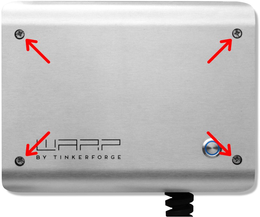
To mount the charger, the cover must be removed. For this, the four Phillips screws must be loosened. After loosening the screws, the cover can be removed from the box.
![]()
The button in the cover is connected via a connection cable and must be disconnected from the cable by pressing the latch.
Additionally, the grounding plug must be unplugged from the front panel. Only then can the cover be completely set aside.
After removing the cover, the housing can be mounted on the wall. The included drilling template can be used for drilling the mounting holes. When mounting, ensure a sufficiently stable surface.
Requirements for Electrical Installation
The selection of the conductor cross-section and circuit protection for the charger supply line must comply with national regulations. A 3-pole miniature circuit breaker with C-characteristic should be used. The charger has internal DC fault current detection, which generates a 70 mA AC fault current at a DC fault current ≥ 6 mA, intended to trip an upstream AC residual current circuit breaker (RCCB).
To guarantee a shutdown in the event of a fault, an upstream Type A 30 mA residual current circuit breaker (RCCB) is necessary.
The charger may only be connected in a TN / TT network.
Electrical Connection
The work described in this section may only be performed by a qualified electrician.
The electrical connection differs for the Basic / Smart variants (without meter) and the Pro variant (with meter).

WARP1 Charger Basic.

WARP1 Charger Pro.
Basic / Smart Variant
After the charger has been mounted, it can now be connected. For this, in addition to the cover, the internal contact protection must also be removed. This is removed by loosening the four slotted screws.
In the Smart variant, a WiFi controller (ESP32 Brick) is connected to the contact protection, to which two cables lead: a two-pole power supply cable and a seven-pole Bricklet cable, via which the connection to the charge controller (EVSE Bricklet) on the DIN rail is established. It is sufficient to simply set the contact protection aside without disconnecting these cables. If the contact protection is nevertheless to be completely removed, these cables must be disconnected. Both cables are best unplugged directly on the left or bottom side of the ESP32 Brick. The Bricklet cable has a small locking button that must be pressed for removal.
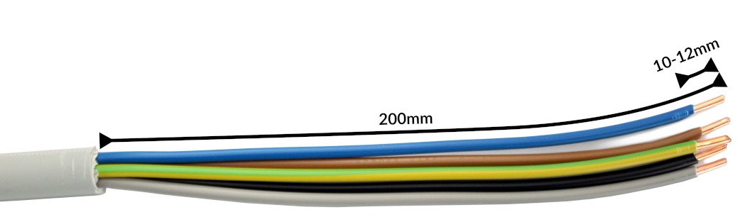
In the Basic and Smart charger variants, the supply line is connected to an internal Phoenix Contact PT 6 terminal block. To offer maximum freedom of movement with rigid conductors, the wires are routed around the terminal block and connected from the rear. We recommend stripping the cable to a length of 20 cm for this. For the PT 6 terminals, the manufacturer specifies a stripping length of 10 mm to 12 mm.
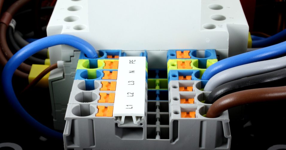
The wires are inserted into the terminals according to the sequence and terminal labels. Afterwards, the wires should be carefully pressed downward so that the front panel can later be reattached over the terminal block. Finally, the cable gland must be tightened. The gland has a clamping range of 11 mm to 22 mm and should be tightened to 10 Nm according to the manufacturer.
The correct seating of the wires and phase assignment must be checked after installation! Then continue with Setting the Charging Current.
Pro Variant
The Pro variant is delivered directly with a 2 m rubber cable of type H07RN-F 5G (4 mm² at 11 kW, 6 mm² at 22 kW). This is connected externally to the supply line, for example via a junction box.
The correct seating of the wires and phase assignment must be checked after installation! Then continue with Setting the Charging Current.
Setting the Charging Current
The maximum allowed charging current must be set depending on the building-side circuit protection. The charging current must not be set higher than allowed by the circuit protection.
To set the charging current, the cover and the internal contact protection must be opened. The contact protection is removed by loosening the four slotted screws. Several cables run from the contact protection into the charger. To set the charging current, the contact protection does not have to be completely removed, so the cables may remain connected.
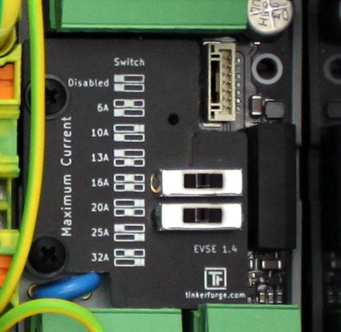
The maximum charging current is set via two slide switches on the internal charge controller (EVSE). The various switch positions are documented next to the switches. The white block represents the position of the switch in each case. In the delivery state, the switches are set so that the charger is inactive. In the photo above, both switches are set to the middle position as an example. This specifies a maximum charging power of 11 kW (16 A).
The switch position and the associated maximum charging current may only be changed after installation by a qualified electrician, taking into account the mentioned conditions!
Testing
Each charger was individually tested at the factory according to IEC 60364-6 and the corresponding valid national regulations; the respective measurement protocol is included. Nevertheless, a test of the entire installation according to the same regulations is necessary before initial commissioning.
In the first approx. 12 seconds after establishing the power supply, the charger performs a DC fault current detection calibration (the charger LED flashes very quickly). A charging process can only begin after this calibration.
When measuring the insulation resistance, a lower value is measured for L1 (approx. 249 kΩ). The reason for this is that the installed charge controller has an optocoupler with a 249 kΩ series resistor between L1 and PE, before and after the contactor (grounding monitoring, contactor monitoring). If an EVSE adapter is used during measurement, erroneous measurements on L2, L3 and N (measured against PE) may occur due to the mentioned monitoring circuit in interaction with the EVSE adapter. If this is the case, the insulation measurement must be performed without an EVSE adapter directly at the Type 2 plug.
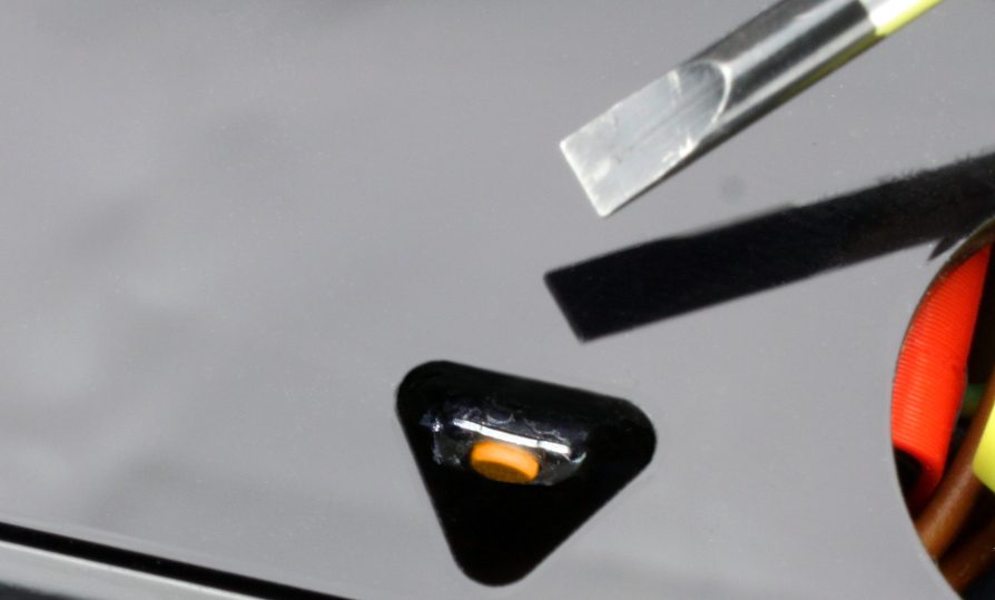
The DC fault current protection can be tested by pressing the orange or black button on the DC fault current protection module (see the following photo). In this case, an AC fault current is generated, which trips the upstream AC residual current circuit breaker. The button must be pressed for up to 10 seconds for an AC fault current to be generated.
Commissioning
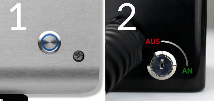
After the charger has been installed and the correct electrical installation has been verified, the charger can be commissioned. In the first step, the power supply to the charger is switched on. The blue LED (1) of the charger then flashes very quickly. The charger performs a calibration of the DC fault current protection device for the first 12 seconds. After completing this calibration, the LED lights up continuously. The charger is now ready for operation. If the LED does not light up permanently, the charger is either disabled via the key switch (2), or an error has been detected (see Troubleshooting).
Next, an electric vehicle can be connected to the charger for charging. To do this, the protective cap is removed from the charging plug and the plug is inserted into the charging socket of the electric vehicle. After a short time, the contactor in the charger should audibly switch and the electric vehicle should indicate the start of the charging process. The charger LED "breathes" during the charging process. When the charging process is finished, the LED lights up permanently. After approx. 15 minutes of inactivity, the LED switches off.
Controls
Pressing the button (1) on the front immediately interrupts an active charging process. Alternatively, the charging cable can be unlocked from the electric vehicle, which also interrupts the charging process. To restart the charging process, in both cases the connection to the vehicle must be disconnected and then reconnected (unplug and replug the cable).
The charging function of the charger can be permanently disabled via the key switch (2) (OFF position). Charging is then only possible again after the key switch has been turned to the ON position.