Assembly and Installation
Scope of Delivery
The WARP Energy Manager 2.0 delivery includes:
- WARP Energy Manager 2.0 (DIN rail module)
- Pluggable screw terminals
- 2-pin screw terminal 5 mm (230 VAC power supply (L+N))
- 4-pin screw terminal 5 mm (2x relay output)
- 4-pin screw terminal 3.5 mm (RS485 Modbus-RTU)
- 4-pin screw terminal 3.5 mm (SG-Ready output)
- 6-pin screw terminal 3.5 mm (4x input)
- Operating manual incl. individual WiFi access data
- RJ45 LAN angle adapter
Installation Location
The WARP Energy Manager 2.0 may only be installed in a suitable distribution cabinet indoors. It must be protected from dust, moisture and improper access. A LAN connection should be made to the WARP Energy Manager, as in many cases a WiFi connection of the WARP Energy Manager is not reliably possible due to the metal shielding of the distribution cabinet.
There must be sufficient space available. No pressure may be exerted on the cables, especially not on the LAN connection. For this reason, we recommend using the included LAN angle adapter.
To mount the WARP Energy Manager, it must be placed on the DIN rail. The housing must be installed so that the LAN connection or DIN rail lock points downward.
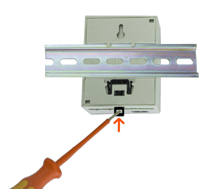
First, the upper bracket is placed on the DIN rail and then the lower one. The energy manager should lock automatically; if this is not the case, you can assist with a screwdriver at the black lock on the bottom.
If the WARP Energy Manager 2.0 is to be removed from the DIN rail again, all supply lines must first be removed (Caution: Ensure voltage-free state!). Then, using a flat-head screwdriver, pull the black spring lock and lift the energy manager from the DIN rail. The lower bracket should be lifted first, followed by the upper bracket.
Electrical Connection
The work described in this chapter may only be performed by a qualified electrician!
Power Supply
After the WARP Energy Manager 2.0 has been mounted, it can be connected. The screw terminals are pluggable, so electrical connection can be made externally. Then the screw terminals can be plugged back into the WARP Energy Manager.
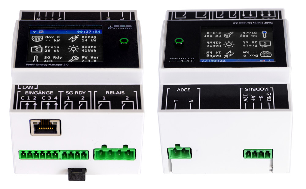
The power supply to the WARP Energy Manager is via a two-pin screw terminal (L+N). The supply line must be protected with a max. 16A circuit breaker with B-characteristic.
The energy manager's power supply is internally protected by a glass fuse (slow-blow (T), 2A).
Modbus (RS485)
A compatible RS485 Modbus-RTU energy meter can be connected to this connection. Compatible energy meters are marked in the list under connection with "WARP Energy Manager". The list of all compatible devices can be found on the Compatible Energy Meters page.
The connector assignment is 12V, A, B, GND. The 12V connection must not be used. A (+), B (-), GND must be connected to the respective energy meter accordingly. Depending on the meter, GND is not connected.
Inputs
The WARP Energy Manager 2.0 has four inputs for potential-free contacts. Normally open or normally closed contacts can be connected to these. The behavior of the energy manager in relation to these inputs can be configured in the web interface. Two inputs each have a Common (C) connection. This must be connected to one side of the normally open/normally closed contact. The other side must then be connected to the respective input.
SG-Ready Output
Heat pumps that can be controlled via an SG-Ready interface can be connected here. For this, the WARP Energy Manager 2.0 offers two relay outputs. Output 1 is activated when operation should be blocked (operating state 1). Output 2 is activated when the heat pump should receive a recommendation to switch on for extended operation for space heating and hot water preparation (operating state 3).
Relay Outputs
With the two potential-free relay switching outputs, up to 230 VAC/ 3A can be switched. These relays are controlled by user-defined rules.
LAN Connection
Control of the chargers is via a network. We recommend connecting the WARP Energy Manager 2.0 via LAN. The LAN connection required for this is located in front of the other connections when installed. To avoid damage, the LAN socket is flexibly mounted. Nevertheless, we recommend not connecting a LAN cable directly to the energy manager, but using the included RJ45 angle adapter between energy manager and LAN cable.
The energy manager is not yet ready for operation! It must now be configured via the web interface.