Assembly and Installation
Scope of Delivery
The stand delivery includes:
- Stand
- If pre-assembled: Selected WARP3 Chargeres incl. accessories
- Mounting materials
- 1x mounting aid
- 4x M8 screws
- 4x washers
- 8x M8 nuts
- Operating manual, operating manuals and test protocols of the chargers
Installation Location
The following requirements must be met for mounting the WARP Charger Stand:
- The installation location must meet all requirements listed in the WARP3 Charger operating manual.
- When installing the stand on a street or public parking lot, open or covered, appropriate impact/ram protection must be installed.
- If multiple stands are to be installed side by side, the distance between the individual stands must be at least 200 mm.
- The surface must be completely level.
Do not install the stand on asphalt! Stability cannot be guaranteed on asphalt.
Creating the Foundation
A concrete foundation is recommended for safe installation of the stand. Design, construction and execution of the foundation are the responsibility of the concrete foundation manufacturer and must be adapted to local conditions if necessary.
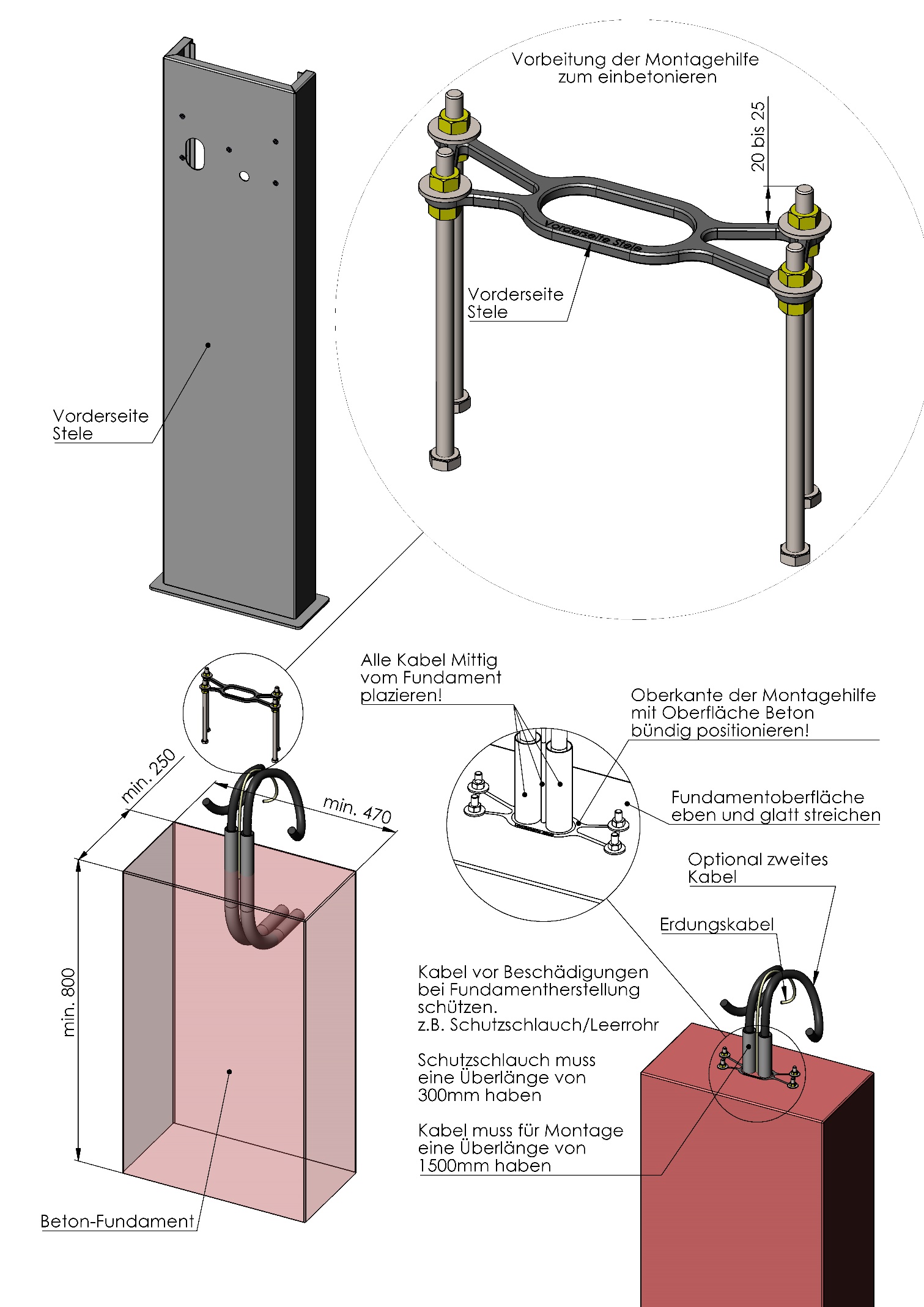
The concrete foundation size of 250 mm x 470 mm x 800 mm should be considered the minimum size to ensure stable standing.
The mounting aid must be assembled as specified with the supplied screws, washers and nuts. The specified dimensions must be observed. Then the assembled mounting aid can be positioned in the concrete foundation.
Water must not accumulate at the foundation; it must be able to drain away. The power supply cables, a grounding cable and any existing network cables must exit at the center of the concrete foundation and have a protruding length of at least 1500 mm. For this purpose, there is an oval recess in the mounting aid with external dimensions of 75 × 35 mm. The foundation manufacturer must ensure adequate protection of the cables. Protective sleeves must protrude at least 300 mm from the concrete. A grounding connection is mandatory.
Mounting the Stand
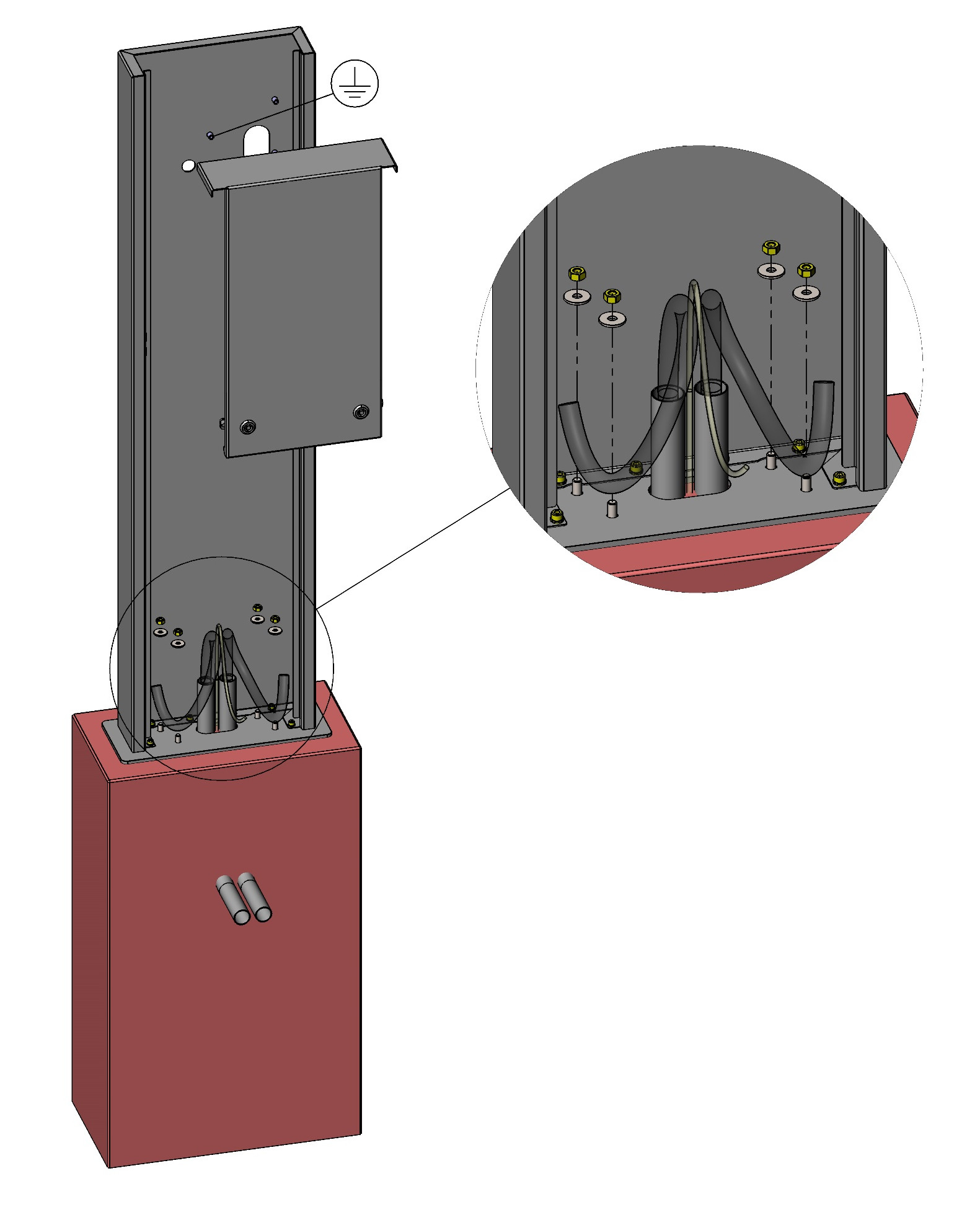
After the concrete foundation has been poured and cured, the stand can be mounted. The rear panels should be removed first. The upper M8 nuts (4 pieces) and washers used in the mounting aid must now be unscrewed again so that the threads are exposed. Then the column can be positioned centrally over the cables protruding from the foundation. The embedded mounting aid ensures correct positioning of the mounting screws. After placing the column on the screws, it can be screwed to the foundation using the previously removed washers and nuts.
Electrical Connection
The electrical connection of the chargeres is made separately for each charger. The electrical installation notes for the WARP3 Charger from the Assembly and Installation Manual must be observed.
Requirements for Electrical Installation
The requirements for electrical installation of the selected WARP3 Charger chargers must be observed.
Electrical Installation
Each charger can be ordered from the factory with a connection cable and connected distribution box. The following describes this variant. Alternatively, the stand can be ordered without pre-installation. The distribution boxes are then missing and the chargeres must be connected directly.
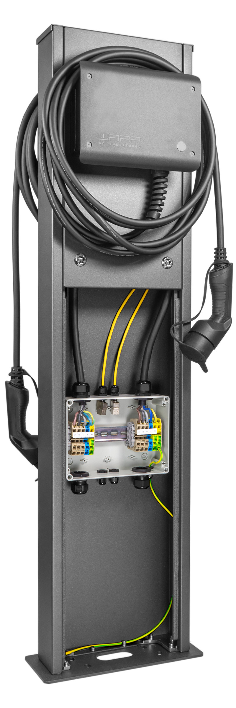
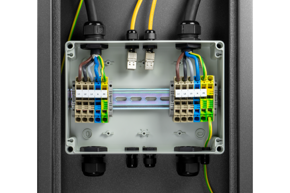
The distribution box contains terminals of type SRK 10 or comparable. Single and multi-core conductors with a cross-section of up to 16 mm² and conductors with ferrules with a cross-section of up to 10 mm² can be connected. The stripping length is 10 mm. Connection is made according to the labeling of the terminals in the distribution box.
Subsequently, the tests required in the WARP3 Charger operating manual must be performed for the chargeres.
Grounding
The stand must definitely be grounded. For this purpose, there is a grounding point in the column at charger height. This must be connected and the grounding verified.
RJ45 - Ethernet
A distribution box is also used for connecting the Ethernet cable. The existing Ethernet cables of the charger can be connected in the box.