Loxone
Introduction
Your WARP Charger is compatible with the Miniserver from Loxone. Loxone is a company that develops and distributes products for building automation.
The WARP Charger can be connected to the Loxone Miniserver via Modbus/TCP or MQTT. Both devices only require a network connection for this.
The WARP Energy Manager and WARP Charger are also compatible with Loxone via MQTT. However, the Miniserver does not include its own MQTT broker, so a broker must first be installed on the network. Setting up MQTT data points must be done completely manually and is therefore only recommended for advanced users.
The Loxone Miniserver also supports EEBUS. This would make it possible to read the electricity meter of the WARP Charger. Unfortunately, a connection to the Loxone Miniserver via EEBUS is very unstable and often fails to establish, so this cannot be recommended at present.
Integration via Modbus/TCP
WARP Charger Configuration
First, the WARP Charger is configured according to the instructions for Modbus/TCP.
The mode must be set to at least read access. If the Miniserver is to control the charger, read/write access must be set.
The WARP Charger register table is selected as the register table.
The WARP Charger is now prepared for Modbus/TCP.
Loxone Miniserver Configuration
We assume that your Loxone Miniserver is already configured and you have already connected with the Loxone Config software.
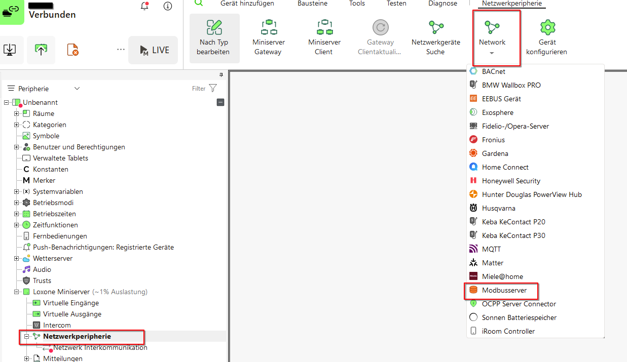
First, a Modbus server is created:
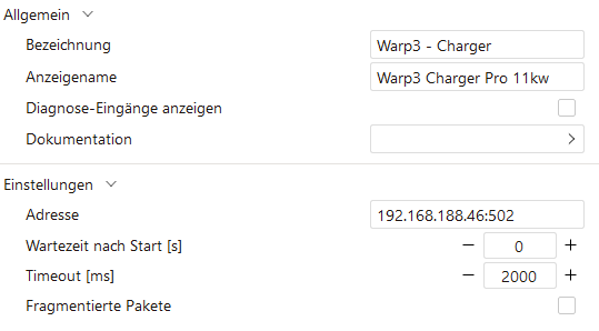
This is configured with the IP address and port.
Next, a Modbus device must be added. To simplify this, we recommend using the WARP templates:
These are imported via the Modbus server.
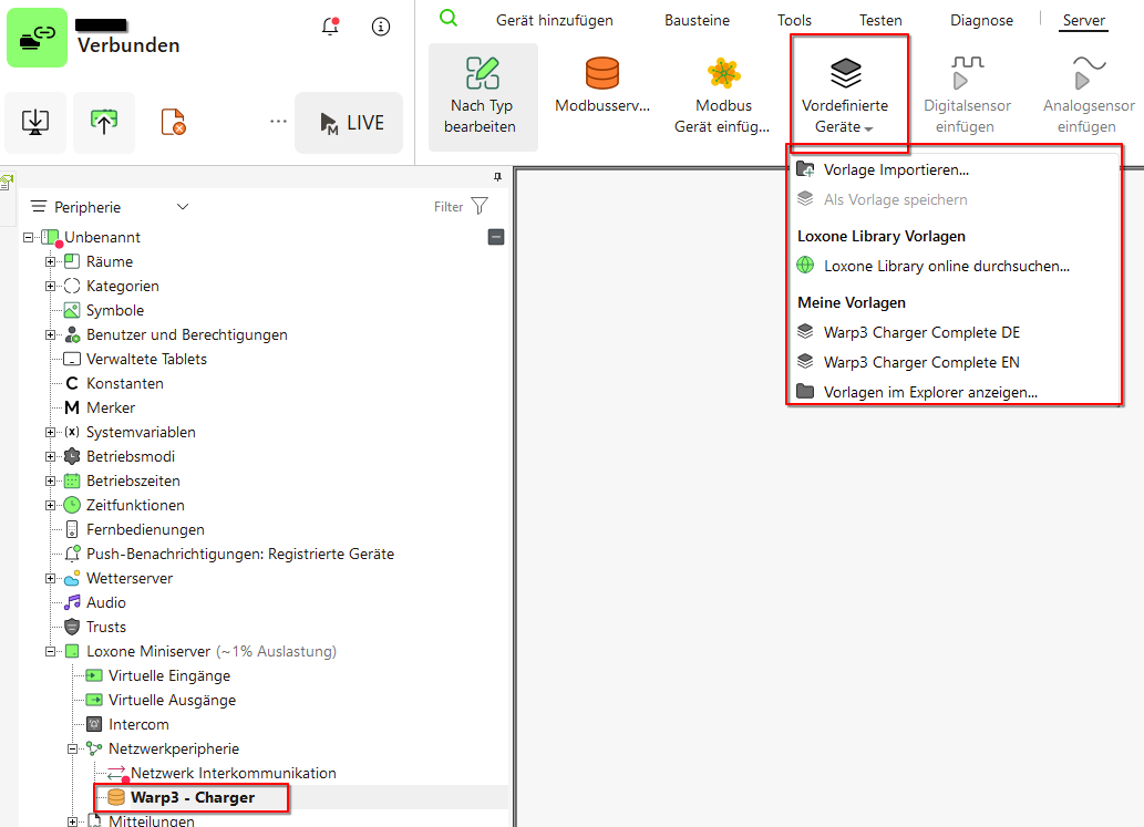
The WARP Charger can then be created directly from a template.
After the device has been created, the configuration should be saved on the Miniserver. A test command can then be sent. Simply select a sensor, right-click, and send a test command. The result can be seen in the Modbus monitor.
The Modbus register table explains the functions and value ranges of the sensors and actuators.
Some Modbus functions are represented via multiple sensors or actuators, as the Miniserver only supports data types from 16 to 64 bits. This data must first be processed using blocks before it can be correctly interpreted or written.
Some register entries are not included in the template. For example, the LED parameters are not included. To control the LED, 160 bits must be written to 10 registers in one command, but the Miniserver can only write a maximum of 64 bits in one command.