Assembly and Installation
Assembly, electrical installation and initial commissioning must be carried out by a qualified electrician. Follow the operating instructions for the stand and the installed WARP4 Chargers.
Opening the Stand
The split rear panel has latches that can be opened with the supplied cabinet key. Remove the lower rear panel before removing the upper one.
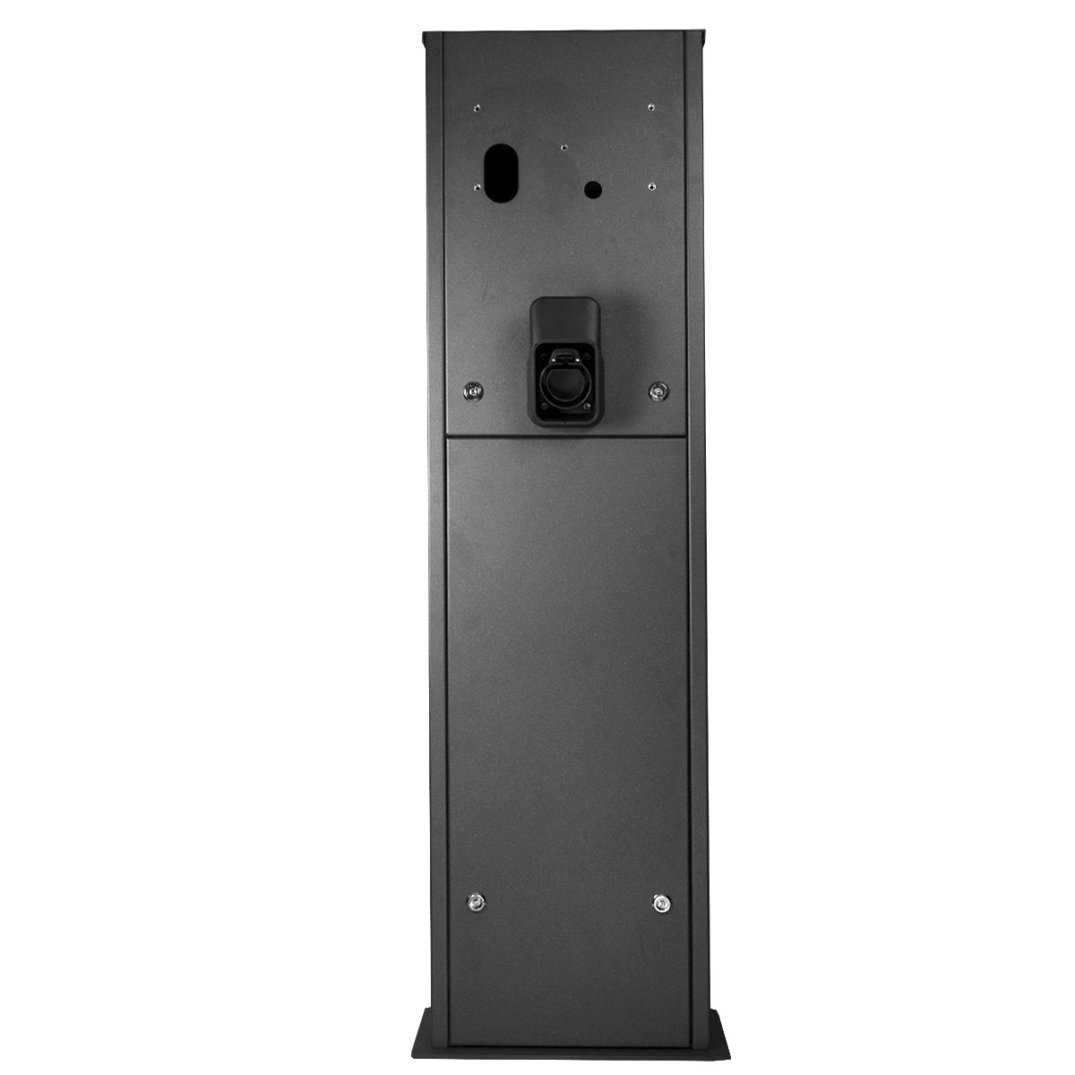
Assembly
Scope of Delivery
Quantities refer to the versions for one or two chargers respectively:
- Stand with base and two rear panels, each with two latches
- Preassembled mounting jig with two braces, four M8 threaded rods, four washers and 16 M8 nuts
- Cabinet key
- One or two cable holders, each with four M6×16 hex-socket screws
- Four or eight M6×35 hex-socket screws for mounting the chargers
- Two or three earthing screw sets, each with one M6×16 hex-socket screw, two M6 washers and one M6 serrated lock washer
- Operating instructions
Only when ordered with the distribution enclosure and cable connection kit, the following are also included:
- Distribution enclosure with DIN rail, one or two terminal blocks and a DIN-rail RJ45 coupler
- Four M6×10 hex-socket screws for mounting the enclosure
- One or two Ethernet patch cables, each 1.5 m long
- One or two charger power cables
- One protective-earth cable for the distribution enclosure
- One or two protective-earth cables to the mounting points behind the chargers
WARP4 Chargers are ordered separately.
Installation Location
- Follow the installation location requirements for the WARP4 Charger.
- Suitable collision protection is required alongside roads and in public parking areas.
- Leave at least 200 mm between stands installed next to each other.
- The mounting surface must be completely level.
Do not install the stand on asphalt, as its stability cannot be ensured there.
Preparing the Foundation
A concrete foundation is recommended for a stable installation. Its design, construction and execution are the responsibility of the foundation contractor and must be adapted to local conditions. The 470 × 250 × 800 mm (width × depth × height) shown in the drawing are minimum dimensions.
The mounting jig is supplied preassembled. Position its top edge flush with the concrete surface, with the threaded rods protruding by 20 to 25 mm as shown in the drawing. Finish the surface level and smooth. Water must be able to drain away rather than collect around the foundation.
Route power, protective-earth and, if used, network cables through the central 110 × 55 mm oval opening. Cables must project at least 1500 mm above the foundation, and protective sleeves or conduits at least 300 mm. Protect the cables from damage during foundation construction. An earth connection is mandatory.
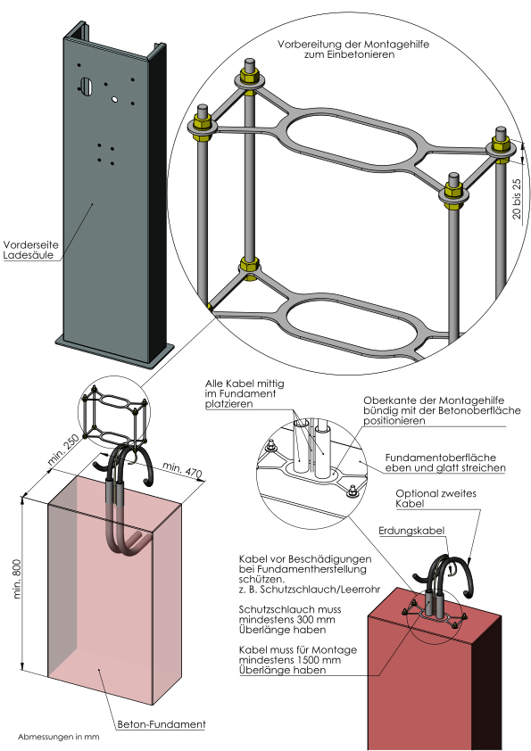
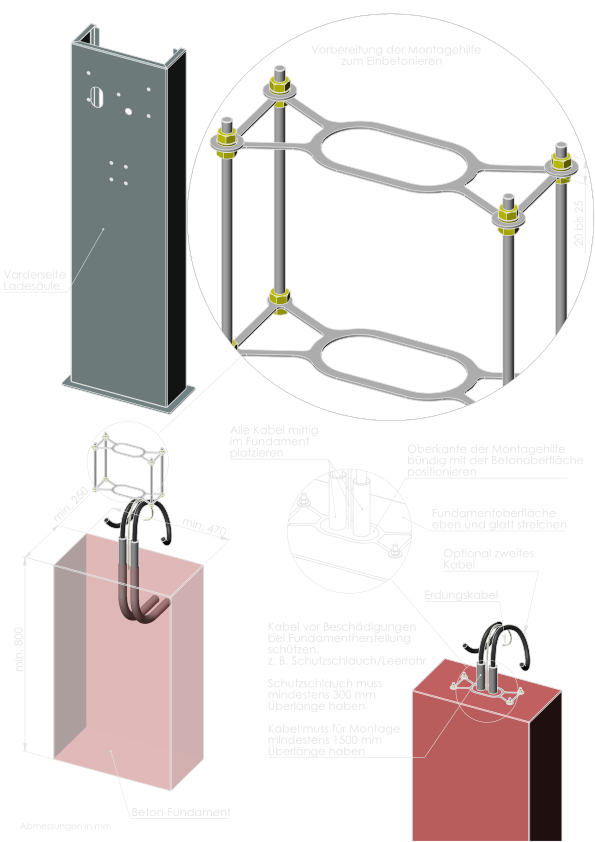
Foundation and dimension drawings (PDF, German labels)
Mounting the Stand
Once the foundation has cured:
- Remove the stand's rear panels.
- Remove the four upper M8 nuts and washers from the mounting jig.
- Lower the stand over the cables and threaded rods projecting from the foundation.
- Secure it with the washers and nuts removed previously.
Mounting the Cable Holder
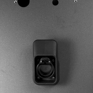
Secure each holder below its charger with the four supplied M6×16 hex-socket screws. Insert the screws from outside through the holder.
Electrical Installation
Each charger is connected separately. Follow the WARP4 Charger electrical installation requirements.
Earthing
The central earthing point is an M6×16 screw in the left-hand base plate. All protective-earth cables meet at this point.
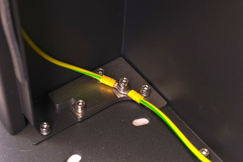
The optional enclosure kit includes a 0.83 m protective-earth cable with an M6 ring terminal and a ferrule. It connects the central point to the enclosure's earth terminal and thus to the supply cable's protective earth. Without the enclosure, this earth connection must be provided by another suitable connection.
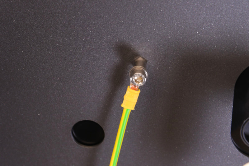
A 1.5 m protective-earth cable with two M6 ring terminals runs from the central point to the M6 nut inside the stand behind the charger. Secure it from inside using an M6×16 screw, serrated lock washer and washers. On the two-charger version, also connect the corresponding point on the upper rear panel.
Mounting and Connecting the Charger
Convert the charger to rear cable entry by exchanging its lower cable glands with the blanking plugs on the rear.
The optional kit's power cables are 0.8 m long, with 12 cm of outer sheath removed at one end and 18 cm at the other. First insert the 18 cm end into the rear of the charger, connect it according to the charger instructions and tighten the gland.
To pass the RJ45 connector through the M25 gland, remove its sealing insert. Slit the insert from its side to the cable hole, fit it around the cable and reinsert it. Tighten the gland and connect the Ethernet patch cable.
Position the charger with its prepared cables on the stand and secure it with four M6×35 hex-socket screws. If using the distribution enclosure, route the 12 cm end of the power cable and the patch cable through its glands and connect them inside. Without the optional kit, prepare suitable connection cables according to the charger instructions.
Optional Distribution Enclosure
Mount the enclosure at the designated points inside the stand below the charger. Remove its lid and secure it with the four supplied M6×10 hex-socket screws.
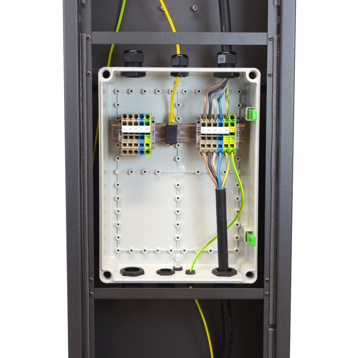
Contaclip ZRK 10/2A terminals or equivalent accept solid and stranded conductors up to 16 mm², or conductors with ferrules up to 10 mm². The stripping length is 10 mm. Connect the conductors according to the terminal labels. Close the lid after connection and testing.
Ethernet
Ethernet cables can be connected in the optional enclosure using the supplied patch cables and DIN-rail RJ45 coupler. Follow the WARP4 Charger LAN instructions.
Testing and Commissioning
After installation, carry out the WARP4 Charger tests. Then commission the chargers according to Configuration and Setup. The stand itself has no software or configuration.