Charge Management
With charge management, it is possible to distribute an available total charging current among up to 64 WARP Chargers. In this case, a WARP Charger or a WARP Energy Manager is configured as the charge manager, which controls the other up to 63 chargers in the cluster and assigns them charging currents.
Without an energy meter at the mains connection, a fixed total current can be distributed, for example to avoid overloading the mains connection. This total current can be set via the web interface and the API.
If a meter is present at the mains connection and can be read by the charge manager (see compatible devices), dynamic load management can be used, which ensures that the mains connection is never overloaded by the WARP Chargers, even when other consumers are switched on or off. Additionally, PV excess charging can then be used.
How It Works
Chargers controlled by charge management only charge when charging current has been authorized by the charge manager. If no charging current has been authorized for a certain time, or the charge manager cannot be reached, the charger automatically stops the charging process. The charge manager in turn stops charging at all controlled chargers if a charger no longer responds or is reached. This ensures that the available current is not exceeded.
The charge manager distributes the available current as fairly as possible between chargers that are charging or ready to charge, ensures that the supply line to the chargers and the mains connection are not overloaded, uses any available PV excess if present (see PV Excess Charging) and attempts to minimize switching operations.
Step 1: Configuration of Externally Controlled Chargers
To use charge management, the external control mode must first be configured
on all chargers that should be controlled under
Energy Management -> Chargers to "externally controlled".
In this mode, a charger only charges when
the charging process is authorized by the charge manager.
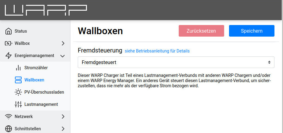
Nothing more needs to be configured for the externally controlled chargers.
Further information is available in the web interface documentation: Chargers
Step 2: Charge Manager Configuration
It is also possible to configure the WARP Energy Manager as a charge manager.
The configuration page can be found there under Energy Management -> Charge Management
and can be configured in the same way as described here.
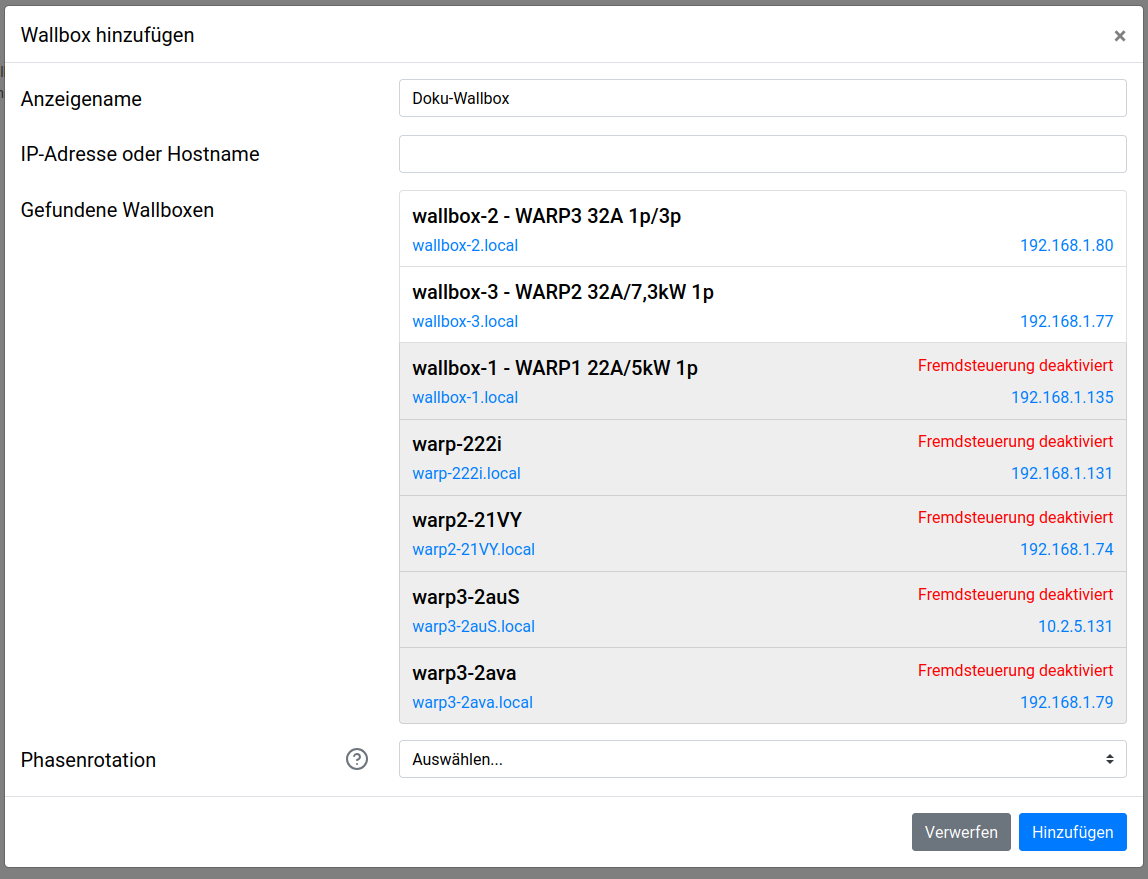
On the charger that should control the other chargers (the charge manager), the external control mode "Charge Manager" must first be selected. Additionally, every charger that should be controlled must be added here as a "Controlled Charger". When clicking on "Add Charger", all chargers that can be reached by the charge manager will appear after a few seconds. By clicking on a found charger, it will be added. Chargers that cannot be added are grayed out.
The phase rotation of a charger can also be configured here, if known. The charge manager can make better decisions when the phase rotation of (some of) the controlled chargers is known. See here for details
After assigning the chargers, the "Maximum Total Current" must be configured. This is typically the load capacity of the common supply line to the chargers.
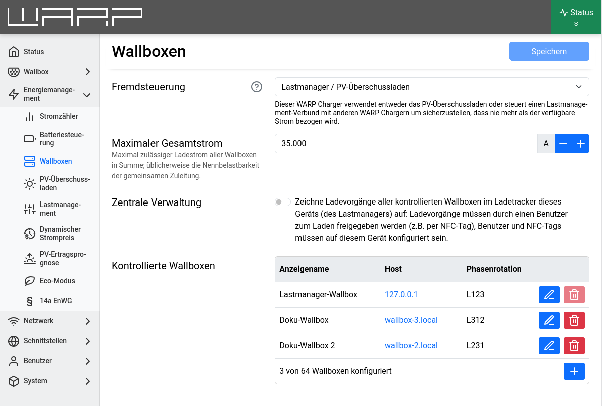
Here the central management can be activated: Charges of controlled chargers are then tracked in the charge manager's charge tracker and users/NFC tags are validated by the charge manager.
Further information is available in the web interface documentation: Charge Management
Step 3: Dynamic Load Management Configuration
To use dynamic load management, an energy meter must first be added that can measure the phase currents at the mains connection. This can also be used for PV excess charging if desired, but dynamic load management can also be used without a PV system. The section Energy Meter Configuration describes how to add a meter.
After a meter has been added, dynamic load management can be activated and configured
on the Energy Management -> Charge Management page.
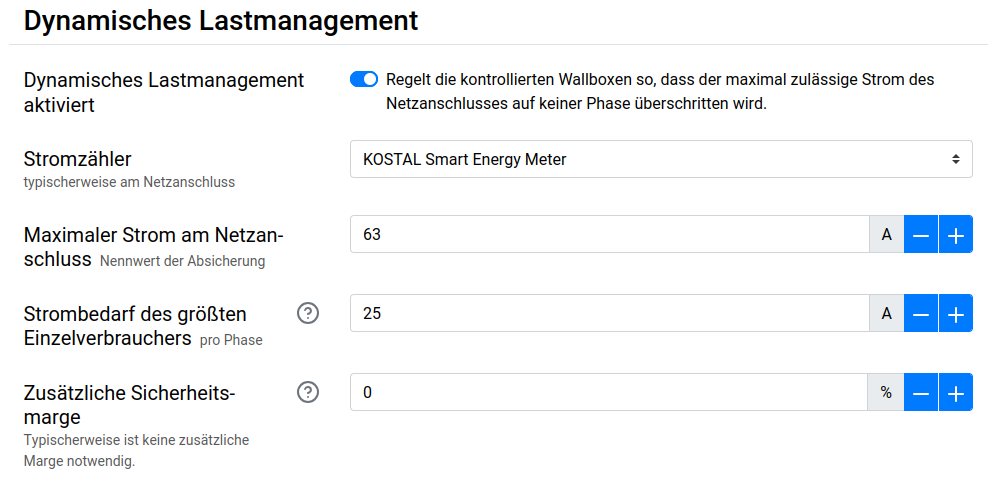
First, the just configured energy meter must be selected.
Then the Maximum Current at Grid Connection must be configured. This is typically the rated value of the circuit breaker. Dynamic load management ensures that this value is not exceeded.
Finally, the expected Power Consumption of the Largest Consumer must be configured. This could be, for example, an instantaneous water heater or a heat pump, but at minimum 16 amperes from a Schuko socket. This value represents the largest expected sudden jump in power consumption at the meter that the dynamic load management must be able to compensate for in the short term (in under 30 seconds).
The chargers controlled by charge management do not need to be taken into account!
Advanced Charge Management Configurations
Additional settings can be found on the Energy Management
-> Charge Management page.
Depending on the use case (e.g. PV excess charging on multiple chargers), the following settings can be helpful. These are not needed for simple charge distribution, e.g. 16 A across two chargers. The options can be found under "Expert Settings".
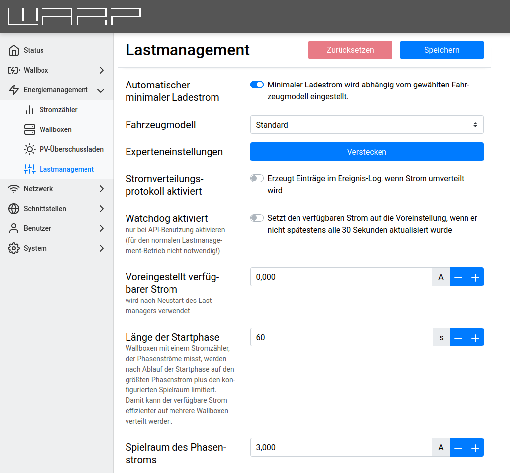
Current Distribution Protocol Enabled
When the current distribution protocol is active, the charge manager adds detailed outputs to the event log whenever current is redistributed. This can be used to investigate unexpected behavior of the charge management.
Watchdog Enabled
The watchdog allows the controlling charger to respond to failures of an external controller. If the available current is not set via the charger API at least every 30 seconds and the watchdog is active, the available current is reset back to the Default Available Current. If the external controller runs again later, the watchdog is reset.
The watchdog should only be enabled when a custom-programmed controller should dynamically change the available current for the charger cluster via the API. For normal charge management operation, the watchdog is not necessary.
Maximum Total Current
The maximum available current is the maximum that can be set as available current via the web interface or the API. Higher currents are not accepted. If an external controller is used, we recommend limiting the maximum available current based on the capacity of the supply lines and the mains connection so that the external controller can never set currents that are too high.
Default Available Current
The default available current is the current that the charge management is allowed to distribute after the controlling charger has been restarted. The available current can be reset via the API, but after a charger restart, the default current is initially used. For example, if an external controller should set the available PV excess current, the default current can be configured to 0, so that charging only starts when the external controller has set the available current at least once.
The default available current cannot be configured if PV excess charging or dynamic load management are being used.
Start Phase Duration and Phase Current Margin
WARP Charger Pro can measure the actual power consumption of the vehicle per phase. With this information, charge management can distribute current more efficiently: If, for example, a vehicle's power consumption drops because the battery is almost full, or a vehicle that can only charge at 16 A is connected to a 22 kW charger, the remaining current can be distributed to other chargers in the charge management cluster.
To allow a vehicle to request more current, charge management must not limit a charger exactly to the actual power consumption (the maximum phase current), but must allow a certain margin so that the vehicle and charge manager can readjust.
For WARP Charger Smart, these settings are not relevant; the charge manager always assumes for chargers without an energy meter that the allocated current is completely used by the vehicle.
The Start Phase Duration indicates how long the actual power consumption of a vehicle is ignored, i.e. the maximum available current is assigned to a charger. The start phase duration should therefore be longer than the start delay of a connected vehicle, so that it can immediately draw the preferred current when charging begins.
The Phase Current Margin indicates how much more current than the vehicle's actual power consumption should be allocated to a charger once the start phase has ended. This margin is necessary so that the vehicle can request more current.
Many vehicles do not charge exactly at the specified charging current, but only support increments of, for example, 0.5 A. Such a vehicle would therefore only charge at 6 A with a current specification of 6.23 A and would need to be allocated more than 6.5 A for it to jump from level 6 A to level 6.5 A. For this vehicle to be able to request more current, the margin would therefore have to be more than 0.5 A.
Minimum Charging Current
The minimum charging current is the current that must be available for a charger in order for it to charge. This current must be at least 6 A. Certain vehicles, however, only charge efficiently at higher currents. With a WARP Charger Pro, the power factor can be determined.
We recommend the automatic setting of the minimum charging current, which depends on the selected vehicle model.
The minimum charging current can also be used to control how many vehicles can charge simultaneously. The maximum number of simultaneous charging processes is "Available Current" divided by "Minimum Charging Current". For example, if the goal is not to charge as many vehicles as possible slowly but simultaneously, but rather to charge multiple vehicles as quickly as possible one after another, the minimum charging current can be set to 32 A.
Phase Rotation
Each controlled charger can be assigned a phase rotation. This indicates how the charger is connected in relation to the mains connection or PV excess meter or to the other chargers. Typically, only clockwise phase rotations are used.
A charger that loads mains connection phase L2 when charging single-phase is, for example, connected with phase rotation L231.
If the phase rotation of all or even just some of the controlled chargers is known, more vehicles can be charged in parallel and PV and mains connection limits can be better utilized: A charger with unknown phase rotation is treated by charge management, when charging single-phase, as if it were loading all three phases.