Upgrade from WARP3 to WARP4
This tutorial shows step by step how a WARP3 Charger is upgraded to the charging electronics of the WARP4 Charger using the WARP3 to WARP4 upgrade kit. Afterwards, many features of the WARP4 Charger are available, in particular the ISO 15118 communication with the vehicle (e.g. for SoC display and Autocharge).
The charging electronics of WARP3 and WARP4 are mechanically compatible. During the upgrade, the complete electronics stack is replaced. All connections have remained identical, so all existing cables can be reused.
The work described in this tutorial should be carried out by a qualified electrician.
Step 1: Configure the upgrade kit
Before installation, the upgrade kit must be configured to match the existing installation. Two things need to be set:
Maximum charging current of the supply line: The four DIP switches on the right of the charge controller (EVSE) are used to set the maximum charging current depending on the circuit breaker of the supply line. The switch positions should be copied from the old WARP3 charging electronics. The meaning of the switch positions is described in the section Setting the Charging Current of the WARP4 manual.

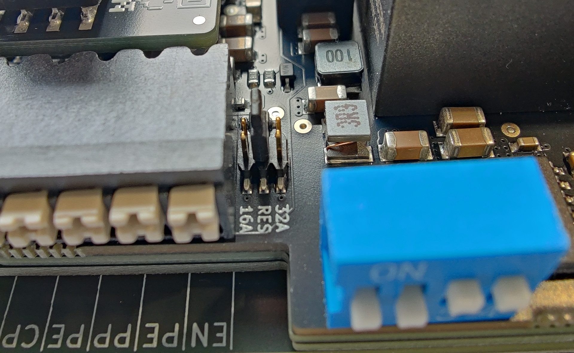
Maximum current of the Type 2 charging cable: Between the DIP switches and the terminal block there is a small jumper. It configures whether a 16 A charging cable (11 kW) or a 32 A charging cable (22 kW) is installed. The jumper is best moved with a pair of small pliers. The correct position is labeled on the circuit board.
On the WARP3, the maximum current of the charging cable was configured via a resistor on the PP input. On the WARP4 this is still possible (middle jumper position), but selecting 16 A or 32 A directly via the jumper is easier.
Step 2: Disconnect the charger from the power supply
Before any further work, the charger must be disconnected from the power supply (switch off the circuit breaker or residual current circuit breaker of the supply line). Verify the absence of voltage before opening the charger.
Step 3: Open the charger
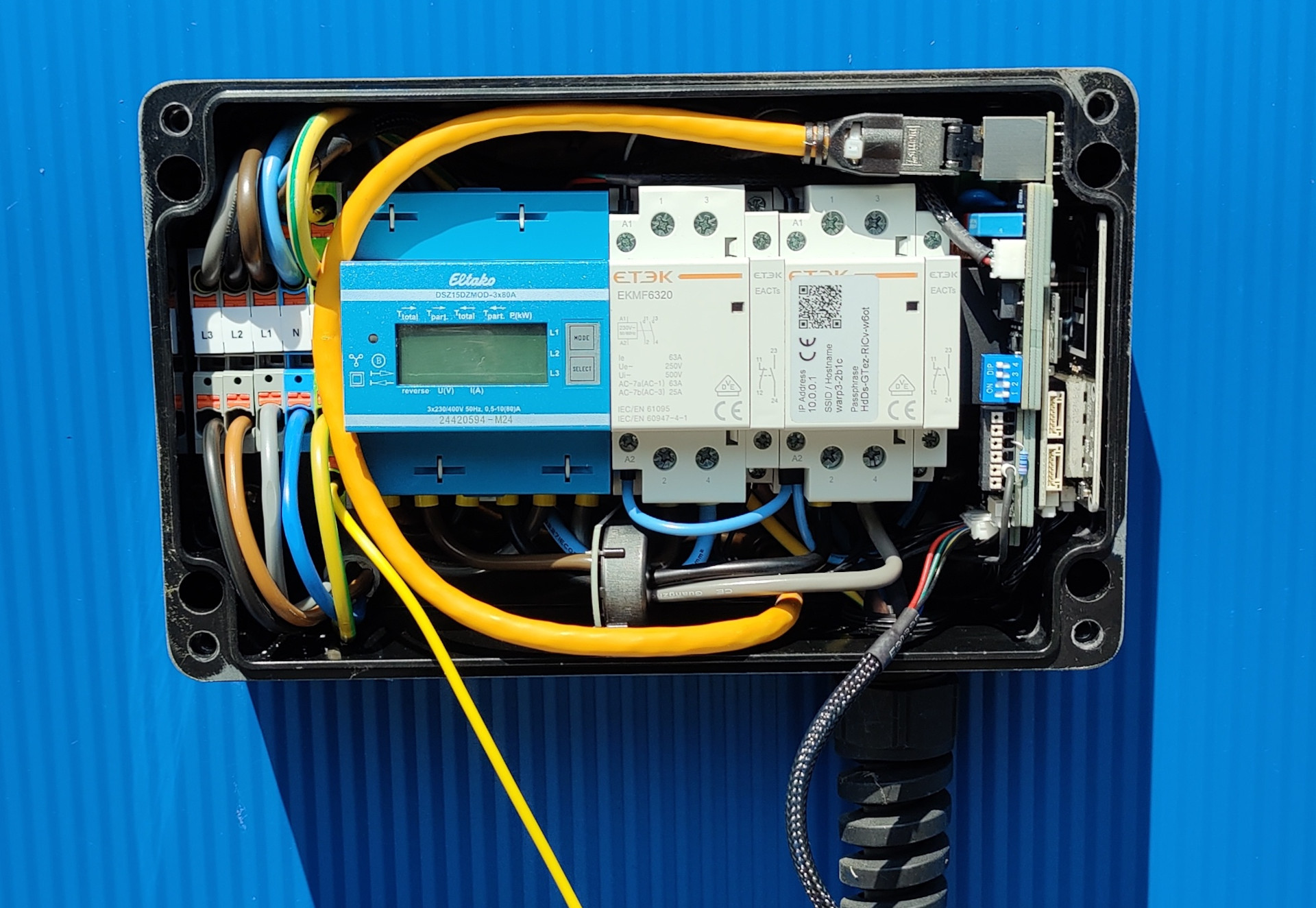
To open the charger, loosen the four Phillips screws of the lid. The button in the lid is connected via a cable and must be released from the cable by pressing the latch lever. In addition, the grounding connector must be unplugged from the front panel. The lid can then be put aside.
Step 4: Remove cables from the charging electronics
The following cables are unplugged from the old charging electronics:
- Ethernet cable
- Modbus cable (WARP3 Charger Pro only: connection to the energy meter)
- CP wire of the Type 2 charging cable
- Cable of the front button
Step 5: Remove the old electronics stack
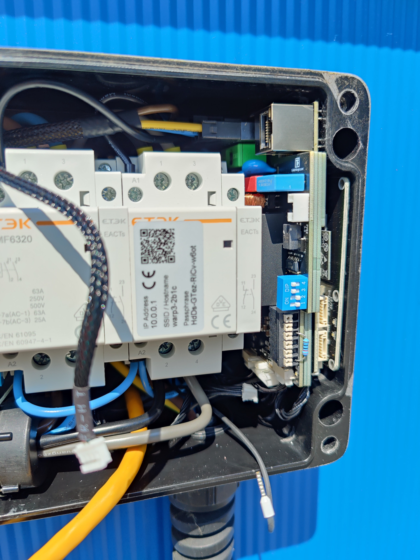
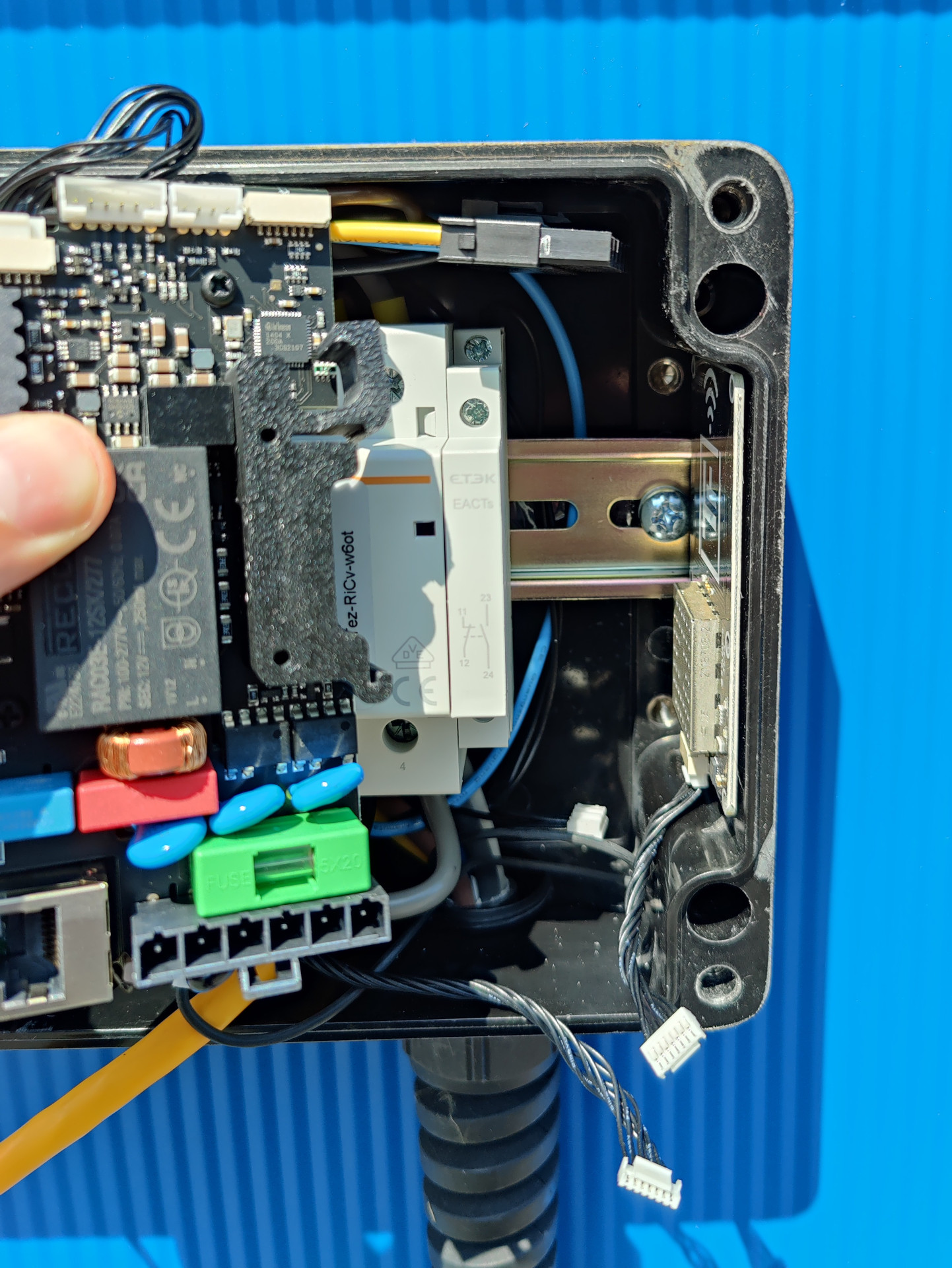
The old electronics stack can now be released from the DIN rail and removed from the charger. While doing so, the following cables are removed, which were hard to reach before:
- Power cable (power supply of the charging electronics)
- Contactor check cable (contactor monitoring)
- Cable to the NFC Bricklet
To release the stack, open the DIN rail holder with a flat-blade screwdriver.
Step 6: Insert the new electronics stack
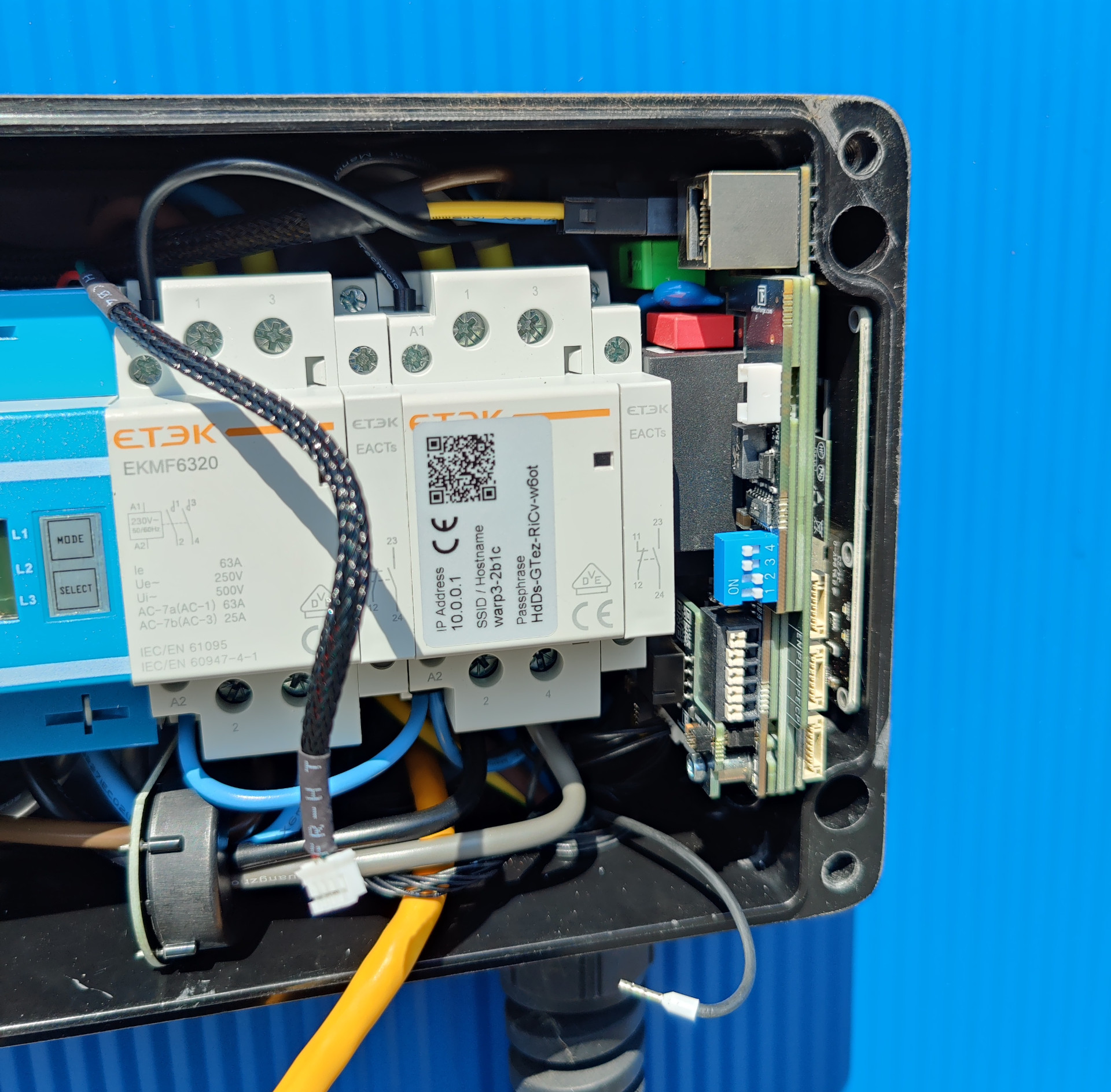
The new WARP4 electronics stack is placed on the DIN rail. While inserting it, the following cables are reconnected before they become hard to reach:
- Power cable
- Contactor check cable
- Cable to the NFC Bricklet
To fasten the new stack after inserting it, push the yellow fastening latch towards the DIN rail with a flat-blade screwdriver.
Step 7: Connect the remaining cables
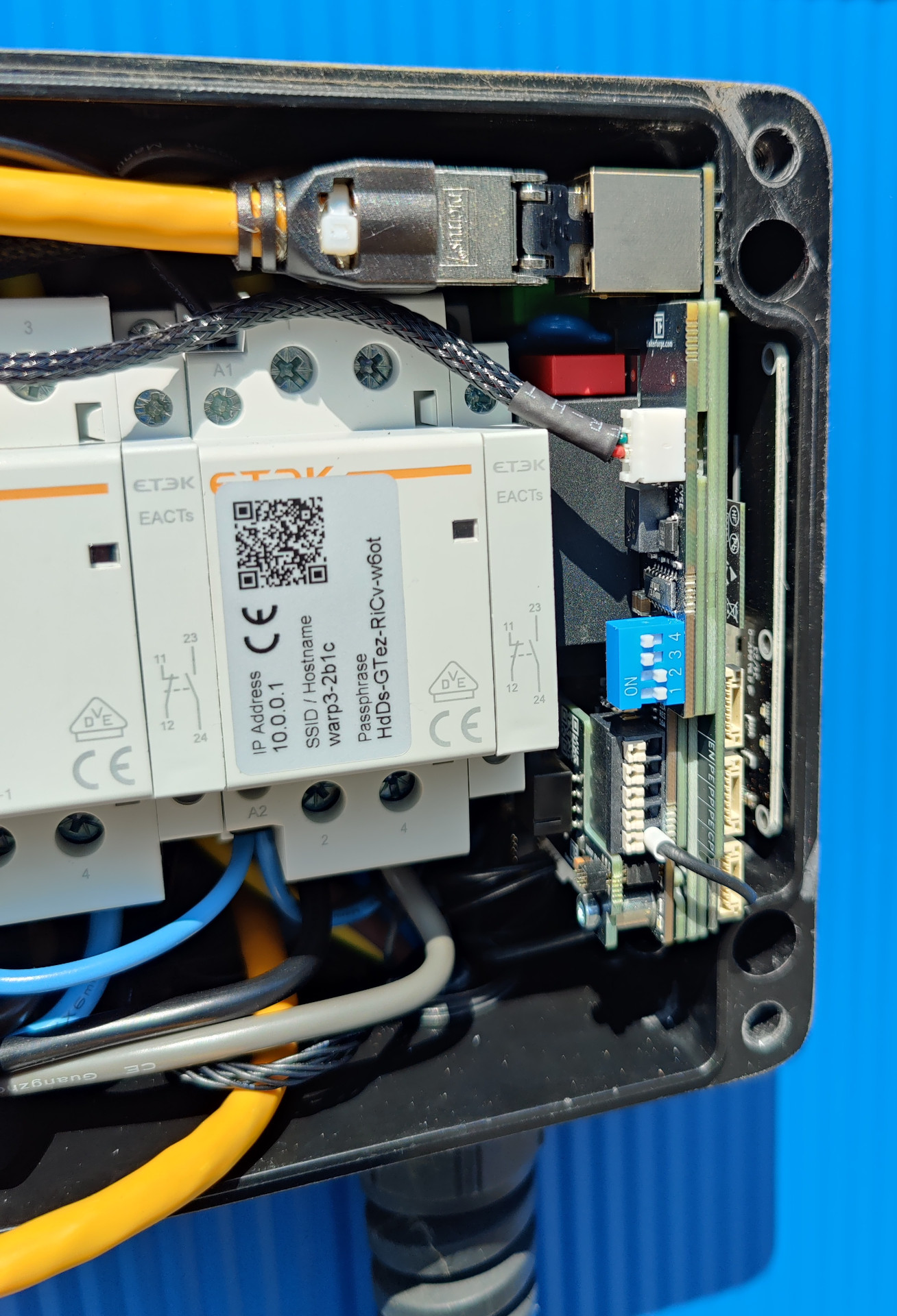
Next, the cables removed in step 4 are reconnected:
- Ethernet cable
- Modbus cable (WARP3 Charger Pro only)
- CP wire of the Type 2 charging cable
- Cable of the front button
The pin assignment of the terminal block is labeled on the circuit board. Check that all connectors are firmly seated.
Step 8: Apply the WARP4 sticker
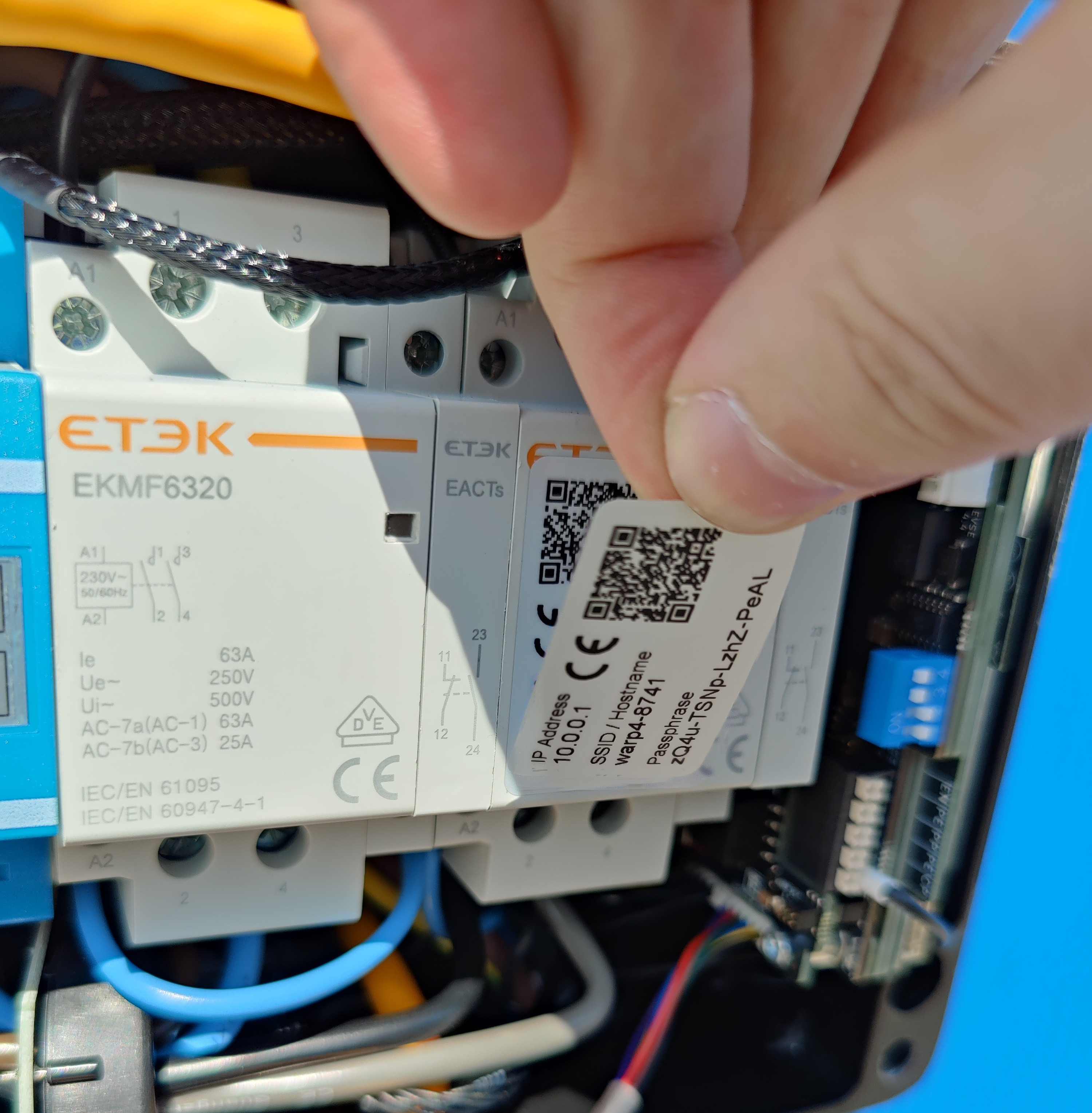
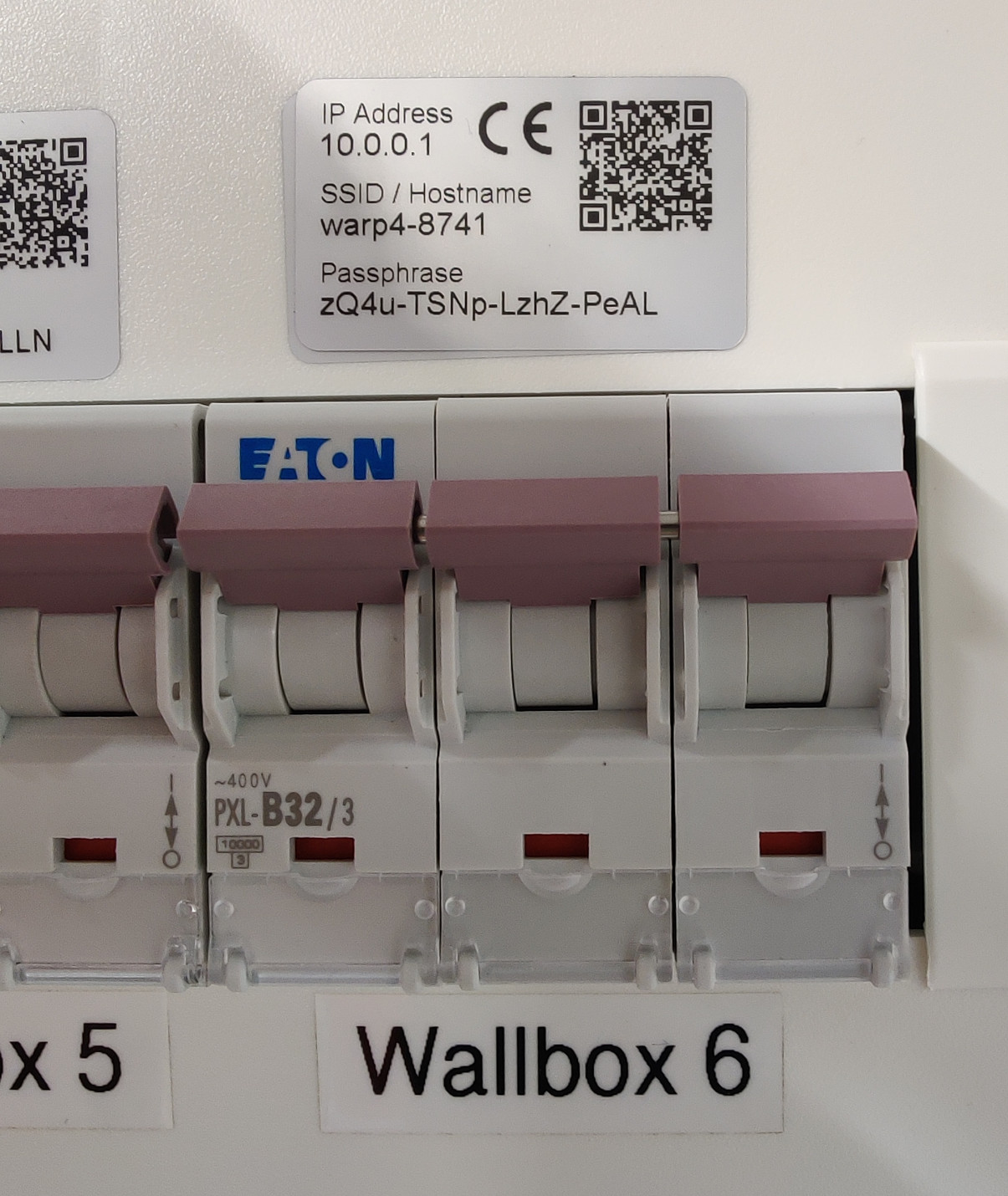
The new charging electronics provide their own WLAN access point with new credentials. The WARP4 sticker with the new WLAN credentials included in the upgrade kit is applied over the existing WARP3 sticker.
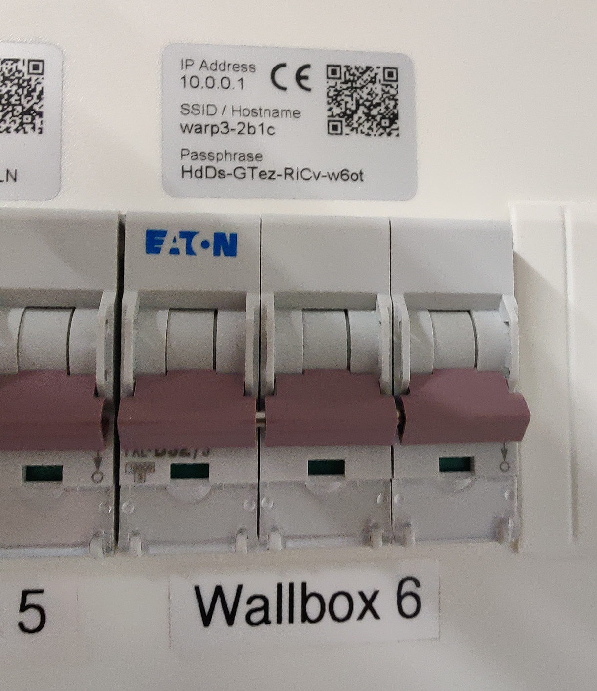
The upgrade kit contains a second sticker with the WLAN credentials. It can be applied over the sticker in the original manual, kept in another easily retrievable place outside of the charger, or for example applied to the circuit breaker in the distribution board (as done in this tutorial, see below).
Step 9: Close the charger
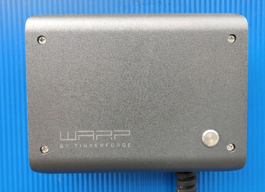
When putting the lid back on, reconnect the cable of the front button and the grounding connector to the front panel. Then fasten the lid with the four Phillips screws.
Step 10: Reconnect the charger to the power supply
The power supply of the charger is switched on again. The LED then blinks magenta while the charger performs a calibration of the DC residual current detection. After the calibration is complete, the LED lights up blue permanently. The charger is now ready for operation.
Commissioning
Commissioning can then be carried out as described in the First Steps tutorial.